Low Latency Ethernet 10G MAC Intel® FPGA IP Design Example User Guide: Agilex™ 3 and Agilex™ 5 FPGAs and SoCs
ID
813665
Date
4/07/2025
Public
A newer version of this document is available. Customers should click here to go to the newest version.
1. Quick Start Guide
2. 10M/100M/1G Ethernet Design Example
3. 1G Ethernet Design Example with IEEE 1588v2 Feature
4. 2.5G Ethernet Design Example
5. 2.5G Ethernet Design Example with IEEE 1588v2 Feature
6. 10G Ethernet Design Example
7. 10M/100M/1G/2.5G/5G/10G (USXGMII) Ethernet Design Example
8. 10M/100M/1G/2.5G/5G/10G (USXGMII) Ethernet Design Example with IEEE 1588 Feature
9. Interface Signals Description
10. Configuration Registers Description
11. Low Latency Ethernet 10G MAC Intel® FPGA IP Design Example User Guide: Agilex™ 3 and Agilex™ 5 FPGAs and SoCs Archives
12. Document Revision History for the Low Latency Ethernet 10G MAC Intel® FPGA IP Design Example User Guide: Agilex™ 3 and Agilex™ 5 FPGAs and SoCs
8.5.1. Test Procedure
Follow these steps to test the design examples in hardware:
- Click Tools > System Debugging Tools > System Console or run command: system-console &.
- Navigate to the hardware design directory: cd <design_example>/LL10G_10G_USXGMII_SM_1588v2/hwtesting/system_console_fm.
- Run the following command in the System Console:
-
source main.tcl
-
set_jtag <select_appropriate_jtag_master>
Note: The set_jtag command places the Agilex™ 5 device on the JTAG chain. -
- Run one of the following commands in the system console to start the test:
- If you want to trigger the test for a specific datarate and channel:
TEST_1588 <from_channel> <to_channel> <speed>
Example: TEST_1588 0 0 1GNote: You must connect the external QSFP28 loopback module to bank 1A before running the test.Table 24. Command Parameters Parameter Valid Values Description channel 0, 1 The channel number to test. speed 100M, 1G, 2P5G, 5G, 10G The PHY speed. Note:- You must connect the external QSFP28 loopback module to the desired QSFP1 port before running the test.
- Burst size is random.
- Two channels are supported—channel 0 and channel 1.
- If you want to trigger the test for a specific datarate and channel:
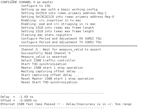
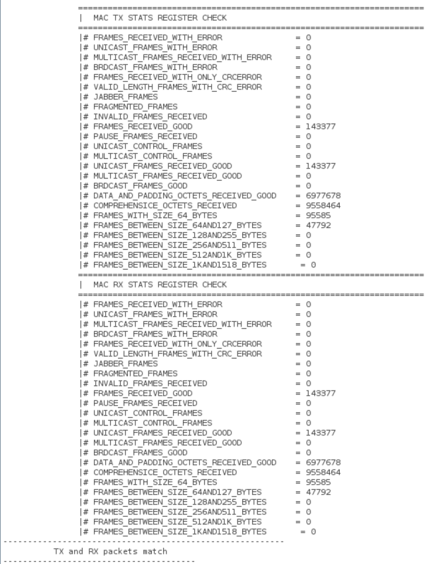
- The following sample output illustrate a successful hardware test run:
Figure 44. Sample Test Output