4.4.1. Steps to Configure the F-Tile PMA/FEC Direct PHY Multirate Intel FPGA IP Core
You can use the following steps to configure the 100G-2 Reconfigurable example.
- Determine the highest data rate for your PMA or FEC direct mode and select the fracture type and the total number of PMA lanes that you want your design to be able to dynamically reconfigure. Select your Reconfiguration group under the General tab based on this requirement.
- Set up the secondary profiles based on the available Reconfiguration subset as defined in Available Reconfiguration Groups for FGT PMA. Determine the fracture type and number of PMA lanes for each reconfiguration profile. Ensure the total PMA lane count configured in your secondary profiles matches the total PMA lane count defined under the Reconfiguration group. Refer to Example 1: Guidelines to configure the Profile #N IP Configuration Parameter Settings for Two PMA Lanes for more information. Take note of the Target fracture and Profile group id settings.
The following figure displays the parameter settings you need to configure in the first two steps.
Figure 14. General and Profile #N IP Configuration Parameter Settings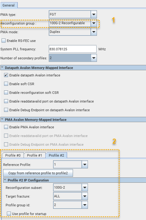
- Verify the base profile (Profile #0) and all secondary profiles settings have no errors or warning messages in the System Messages pane of the IP Parameter Editor. This includes ensuring valid Common Datapath Options, TX Datapath Options, RX Datapath Options and RS-FEC parameter settings for all reconfiguration profiles.
- Ensure you select the Enable datapath Avalon interface, Enable reconfiguration soft CSR and Enable soft CSR (optional) to reconfigure your design.
- Generate the F-Tile PMA/FEC Direct PHY Multirate Intel FPGA IP Core.
The following figure displays the parameter settings you need to configure in the remaining steps.
Figure 15. Datapath Avalon Memory-Mapped Interface, Profile #N Common, TX/RX Datapath and RS-FEC Parameter Settings - Make the following .qsf setting assignment that is required for a design using the F-Tile PMA/FEC Direct PHY Multirate Intel FPGA IP and the F-Tile Dynamic Reconfiguration Suite Intel FPGA IP.
set_instance_assignment -name IP_COLOCATE F_TILE -from dr_dut|dr_f_0 -to dut|directphy_f_dr_0
The following example demonstrates one valid set of parameter settings for the F-Tile PMA/FEC Direct PHY Multirate Intel FPGA IP. The example parameter settings are for a 100G-2 Reconfigurable group with two secondary reconfiguration profiles.
| General Parameters |
|||
|---|---|---|---|
| PMA type : FGT | |||
| Reconfiguration group : 100G-2 Reconfigurable | |||
| PMA mode : Duplex | |||
| Enable RS-FEC use : Off | |||
| System PLL frequency : 830.078125 MHz | |||
| Number of Secondary Profiles : 2 | |||
| Enable datapath Avalon interface : On | |||
| Enable Soft CSR : On | |||
| Enable reconfiguration soft CSR : On | |||
| Enable readdatavalid port on datapath Avalon interface : Off | |||
| Enable Debug Endpoint on datapath Avalon interface : Off | |||
| Enable PMA Avalon interface : On | |||
| Enable readdatavalid port on PMA Avalon interface : Off | |||
| Enable Debug Endpoint on PMA Avalon interface : Off | |||
| Profile Parameters | Profile #0 | Profile #1 | Profile #2 |
| Reconfiguration subset | 100G-2 | 25G-1 | 25G-1 |
| Target fracture | All | 0 | 1 |
| Profile group id | 0 | 1 | 1 |
| Use profile for startup | Disabled | Enabled | Enabled |
| Common datapath options | |||
| Number of PMA lanes | 2 | 1 | 1 |
| FGT PMA configuration rules | basic | basic | basic |
| PMA modulation type | PAM4 | NRZ | NRZ |
| PMA data rate | 53125 | 26562.5 | 26562.5 |
| PMA width | 64 | 32 | 32 |
| Lane location | |||
| Logical PMA Lane location | 0,1 |
0 |
1 |
Example 1: Guidelines to configure the Profile #N IP Configuration Parameter Settings for Two PMA Lanes
The following steps explain how to configure the base (Profile #0) and secondary profiles (Profile #N) for the 100G-2 Reconfigurable reconfiguration group.
- For Profile #0 the Reconfiguration subset, Target fracture and Profile group id parameters are automatically populated to match the Reconfiguration group setting of 100G-2 and only the Use profile for startup parameter is selectable. The ALL setting for the Target fracture implies that the settings selected under this profile are applied to all PMA lanes of the configuration. The Use profile for startup is not selected and so this profile is not used for startup.
Figure 16. Profile #1 IP Configuration Settings
- For Profile #1 the Reconfiguration subset parameter is set to 25G-1, the Target fracture parameter is set to 0, and the Profile group id parameter is set to 1. Since the Target fracture is set to 0, this profile is placed at logical PMA lane 0.
Figure 17. Profile #1 IP Configuration Settings
- For Profile #2 the Reconfiguration subset parameter is again set to 25G-1, the Target fracture parameter is set to 1, and the Profile group id parameter is set to 1. Since the Target fracture is set to 1, this profile is placed at logical PMA lane 1.
Figure 18. Profile #2 IP Configuration Settings
Note: The Profile group id is set to 1 for both Profile #1 and Profile #2. This is a requirement to ensure the total PMA lanes configured with the same Profile group id matches the total PMA lane count defined under the Reconfiguration group.
Example 2: Guidelines to configure the Profile #N IP Configuration Parameter Settings for Four PMA Lanes
This section demonstrates another example on how to configure secondary profiles (Profile #N) for the 100G-4 Reconfigurable reconfiguration group.
- For Profile #1 the Reconfiguration subset parameter is set to 50G-2, the Target fracture parameter is set to 0, and the Profile group id parameter is set to 1. Since the Target fracture is set to 0, and the profile defines two PMA lanes, they are placed at logical PMA lane 0 and logical PMA lane 1.
Figure 19. Profile #1 IP Configuration Settings
- For Profile #2 the Reconfiguration subset parameter is again set to 50G-2, the Target fracture parameter is set to 1, and the Profile group id parameter is also set to 1. Since the Target fracture is set to 1, and the profile defines two PMA lanes, they are placed contiguously at logical PMA lane 2 and logical PMA lane 3.
Figure 20. Profile #2 IP Configuration SettingsNote: The Profile group id is set to 1 for both Profile #1 and Profile #2. This is a requirement to ensure total PMA lanes configured with the same Profile group id matches the total PMA lane count defined under Reconfiguration group. In this case, it is four PMA lane count to match the 100G-4 Reconfigurable group.
- For Profile #3 the Reconfiguration subset parameter is again set to 50G-2, but the Target fracture parameter is set to ALL, and the Profile group id parameter is set to 2. Four lanes are required to match the total PMA lanes defined for the 100G-4 Reconfigurable reconfiguration group. Since the Target fracture is set to ALL, four PMA lanes are placed contiguously at logical PMA lane 0, logical PMA lane 1, logical PMA lane 2, and logical PMA lane 3 and the same settings defined under the Common Datapath Options, TX Datapath Options, RX Datapath Options and RS-FEC tabs are applied to all PMA lanes.
Figure 21. Profile #3 IP Configuration Settings