1.1.2. Dielectric Constant
The dielectric Constant (Ɛr or Dk in many material data sheets) is a measure of the insulating properties of the material and affects the capacitance of the conductor embedded within it as well as the speed of signal propagation on the transmission line. Lower dielectric constant provides better insulation, faster signal propagation, higher trace impedance for a given trace geometry and smaller stray capacitance.
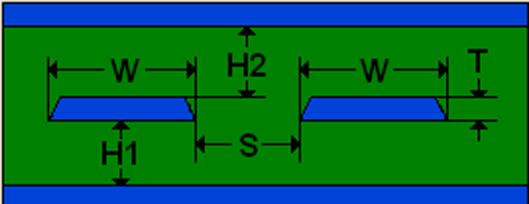
| Material | Er | W (mils) | S (mils) | T (mils) | H1 (mils) | H2 (mils) | Zo (Ω) | Zdiff (Ω) | Tpd (ps/in) | C (pF/in) |
|---|---|---|---|---|---|---|---|---|---|---|
| FR4 | 4.6 | 6 | 15 | 0.7 | 7 | 11 | 52 | 100 | 182 | 3.5 |
| Meg-6 | 3.4 | 6 | 15 | 0.7 | 5 | 8 | 100 | 156 | 3.1 |
Consider a 100-Ω differential stripline pair constructed with an optimal trace width (W) of 6 mils and pair separation (S) of 15 mils. For FR4, the total dielectric thickness is 18.7 mils (T+H1+H2). For the same trace construction dimensions using Megtron-6 the total thickness is 13.7 mils. This reduction of total thickness by 5 mils is significant because it quickly adds up for high density boards that require many signal layers. For instance, a typical FPGA board with 6 stripline routing layers can result in 30 mils of PCB thickness savings using the Megtron 6 vs. FR4. This can be the difference between boards that are easily manufactured using standard via drilling processes vs. ones that require more expensive laser drilling techniques because of the smaller board thickness to via aspect ratio. Furthermore, lower Ɛr results in faster signal propagation (Tpd) and lower trace capacitance (C), which improves signal performance.
An additional consideration for Ɛr is that it usually decreases as frequency increases. Decreasing Ɛr affects the transmission line in two ways:
- The trace impedance increases with decreasing Ɛr causing reflections that further degrade signal quality
- The signal velocity increases with decreasing Ɛr causing dispersion of the different harmonics that comprise the digital signal. This results in increased phase jitter at the receiver