AN 672: Transceiver Link Design Guidelines for High-Gbps Data Rate Transmission
ID
683624
Date
1/29/2020
Public
1.3.2.1. Trace Width Selection
PCBs are becoming very constrained, and using fine trace widths down to 4 mils wide is commonly used to improve routability. However, for high-speed signals, narrow trace geometries increases conductor loss due to skin effect. As a result, routabilty must be properly balanced with trace width selection for better performance. Larger signal attenuation occurs for signals at 4 mils vs. 5 to 6 mils. For example, for a 28-Gbps signal, the difference in attenuation at the Nyquist frequency (14 MHz) is approximately 3 dB for 4 mils versus 6 mils wide trace.
Figure 15. Trace Width vs. Signal Attenuation
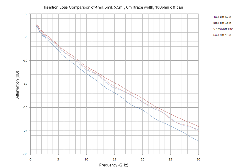
Note: For high-speed transceiver signals, use trace widths of 6 mils or more to reduce conductor loss.
Note: Limit the use of 4 mil trace widths to the BGA breakout area and keep their trace length as short as possible.