Intel® Quartus® Prime Pro Edition User Guide: Timing Analyzer
ID
683243
Date
3/28/2022
Public
A newer version of this document is available. Customers should click here to go to the newest version.
2.2.1. Timing Path and Clock Analysis
2.2.2. Clock Setup Analysis
2.2.3. Clock Hold Analysis
2.2.4. Recovery and Removal Analysis
2.2.5. Multicycle Path Analysis
2.2.6. Metastability Analysis
2.2.7. Timing Pessimism
2.2.8. Clock-As-Data Analysis
2.2.9. Multicorner Timing Analysis
2.2.10. Time Borrowing
3.1. Timing Analysis Flow
3.2. Step 1: Specify Timing Analyzer Settings
3.3. Step 2: Specify Timing Constraints
3.4. Step 3: Run the Timing Analyzer
3.5. Step 4: Analyze Timing Reports
3.6. Applying Timing Constraints
3.7. Timing Analyzer Tcl Commands
3.8. Timing Analysis of Imported Compilation Results
3.9. Using the Intel® Quartus® Prime Timing Analyzer Document Revision History
3.10. Intel® Quartus® Prime Pro Edition User Guide: Timing Analyzer Archive
3.5.1.1. Report Fmax Summary
3.5.1.2. Report Timing
3.5.1.3. Report Timing By Source Files
3.5.1.4. Report Data Delay
3.5.1.5. Report Net Delay
3.5.1.6. Report Clocks and Clock Network
3.5.1.7. Report Clock Transfers
3.5.1.8. Report Metastability
3.5.1.9. Report CDC Viewer
3.5.1.10. Report Asynchronous CDC
3.5.1.11. Report Logic Depth
3.5.1.12. Report Neighbor Paths
3.5.1.13. Report Register Spread
3.5.1.14. Report Route Net of Interest
3.5.1.15. Report Retiming Restrictions
3.5.1.16. Report Reset Statistics
3.5.1.17. Report Pipelining Information
3.5.1.18. Report Time Borrowing Data
3.5.1.19. Report Exceptions and Exceptions Reachability
3.5.1.20. Report Bottlenecks
3.6.1. Recommended Initial SDC Constraints
3.6.2. SDC File Precedence
3.6.3. Modifying Iterative Constraints
3.6.4. Using Entity-bound SDC Files
3.6.5. Creating Clocks and Clock Constraints
3.6.6. Creating I/O Constraints
3.6.7. Creating Delay and Skew Constraints
3.6.8. Creating Timing Exceptions
3.6.9. Using Fitter Overconstraints
3.6.10. Example Circuit and SDC File
3.6.8.5.1. Default Multicycle Analysis
3.6.8.5.2. End Multicycle Setup = 2 and End Multicycle Hold = 0
3.6.8.5.3. End Multicycle Setup = 2 and End Multicycle Hold = 1
3.6.8.5.4. Same Frequency Clocks with Destination Clock Offset
3.6.8.5.5. Destination Clock Frequency is a Multiple of the Source Clock Frequency
3.6.8.5.6. Destination Clock Frequency is a Multiple of the Source Clock Frequency with an Offset
3.6.8.5.7. Source Clock Frequency is a Multiple of the Destination Clock Frequency
3.6.8.5.8. Source Clock Frequency is a Multiple of the Destination Clock Frequency with an Offset
3.6.8.5.1. Default Multicycle Analysis
By default, the Timing Analyzer performs a single-cycle analysis to determine the setup and hold checks. Also, by default, the Timing Analyzer sets the end multicycle setup assignment value to one and the end multicycle hold assignment value to zero.
The source and the destination timing waveform for the source register and destination register, respectively where HC1 and HC2 are hold checks 1 and 2 and SC is the setup check.
Figure 112. Default Timing DiagramThe timing waveforms show the source and destination registers of a data transfer. HC1 and HC2 are the hold checks that Timing Analyzer performs. SC is the setup check that Timing Analyzer performs.
Figure 113. Setup Check Calculation
The most restrictive default single-cycle setup relationship, with an implied end multicycle setup assignment of one, is 10 ns.
Figure 114. Default Setup Report
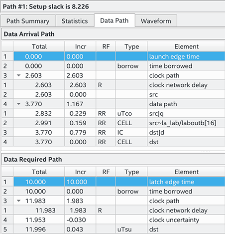
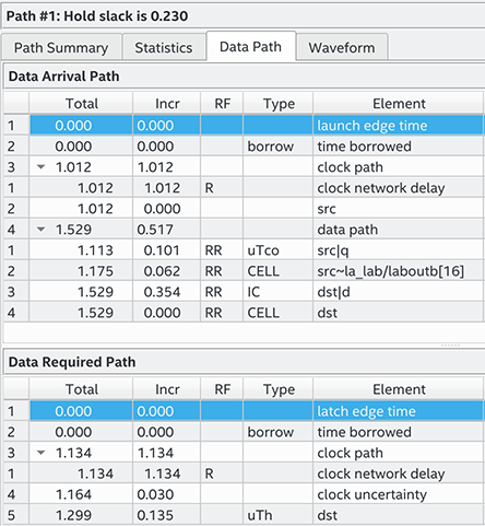
Figure 115. Hold Check CalculationThe figure shows the setup timing report with the launch and latch edge times highlighted.
The most restrictive default single-cycle hold relationship, with an implied end multicycle hold assignment of zero, is 0ns.
Figure 116. Default Hold Report The figure shows the hold timing report with the launch and latch edge times highlighted.