Intel Acceleration Stack for Intel® Xeon® CPU with FPGAs Core Cache Interface (CCI-P) Reference Manual
ID
683193
Date
11/04/2019
Public
1.3.1. Signaling Information
1.3.2. Read and Write to Main Memory
1.3.3. Interrupts
1.3.4. UMsg
1.3.5. MMIO Accesses to I/O Memory
1.3.6. CCI-P Tx Signals
1.3.7. Tx Header Format
1.3.8. CCI-P Rx Signals
1.3.9. Multi-Cache Line Memory Requests
1.3.10. Byte Enable Memory Request ( Intel® FPGA PAC D5005)
1.3.11. Additional Control Signals
1.3.12. Protocol Flow
1.3.13. Ordering Rules
1.3.14. Timing Diagram
1.3.15. CCI-P Guidance
1.3.1. Signaling Information
- All CCI-P signals must be synchronous to pClk.
- Intel® recommends using the CCI-P structures defined inside ccip_if_pkg.sv file. This file can be found in the RTL package.
- All AFU input and output signals must be registered.
- AFU output bits marked as RSVD are reserved and must be driven to 0.
- AFU output bits marked as RSVD-DNC, are don’t care bits. The AFU can drive either 0 or 1.
- AFU input bits marked as RSVD must be treated as don’t care (X) by the AFU.
- All signals are active high, unless explicitly mentioned. Active low signals use a suffix _n.
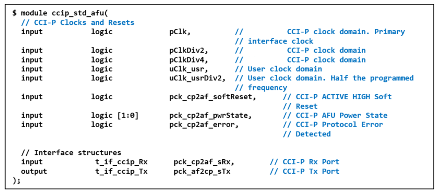
The figure below shows the port map for the ccip_std_afu module. The AFU must be instantiated under here. The subsequent sections explain the interface signals.
Figure 7. ccip_std_afu Port Map