Intel Acceleration Stack for Intel® Xeon® CPU with FPGAs Core Cache Interface (CCI-P) Reference Manual
1.3.6. CCI-P Tx Signals
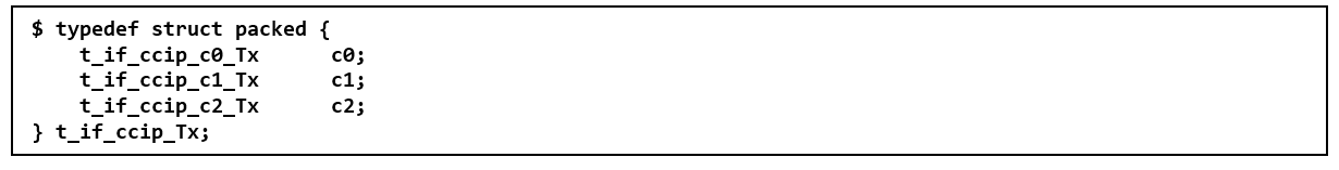
There are three Tx channels:
The C0 and C1 Tx channels are used for memory requests. Both C0 and C1 Tx channels have independent flow control. The C0 Tx channel is used for memory read requests; the C1 Tx channel is used for memory write requests.
The C2 Tx channel is used to return MMIO Read response to the FIU. The CCI-P port guarantees to accept responses on C2; therefore, it has no flow control.

Each Tx channel has a valid signal to qualify the corresponding header and data signals within the structure.
The following tables describe the signals that make up the CCI-P Tx interface.
| Signal | Width (bits) | Direction | Description |
|---|---|---|---|
| pck_af2cp_sTx.c0.hdr | 74 | Output | Channel 0 request header. Refer to Table 18. |
| pck_af2cp_sTx.c0.valid | 1 | Output | When set to 1, it indicates channel 0 request header is valid. |
| pck_cp2af_sRx.c0TxAlmFull | 1 | Input | When set to 1, Tx Channel 0 is almost full. After this signal is set, AFU is allowed to send a maximum of 8 requests. When set to 0, AFU can start sending requests immediately. |
| Signal | Width | Direction | Description |
|---|---|---|---|
| pck_af2cp_sTx.c1.hdr | 80 | Output | Channel 1 request header. Refer to Table 12. |
| pck_af2cp_sTx.c1.data | 512 | Output | Channel 1 data |
| pck_af2cp_sTx.c1.valid | 1 | Output | When set to 1, it indicates channel 1 request header and data is valid. |
| pck_cp2af_sRx.c1TxAlmFull | 1 | Input | When set to 1, Tx Channel 1 is almost full. After this signal is set, AFU is allowed to send a maximum of 8 requests or data. When set to 0, AFU can start sending requests immediately. |
| Signal | Width (bits) | Direction | Description |
|---|---|---|---|
| pck_af2cp_sTx.c2.hdr | 9 | Output | Channel 2 response header. Refer to Table 12. |
| pck_af2cp_sTx.c2.mmioRdValid | 1 | Output | When set to 1, indicates Channel 2 response header and data is valid. |
| pck_af2cp_sTx.c2.data | 64 | Output | Channel 2 data. MMIO Read Data that AFU returns to FIU. For 4 bytes reads, data must be driven on bits [31:0]. For 8 bytes reads, AFU must drive one 8 bytes data response. Response cannot be split into two 4 bytes responses. |