External Memory Interfaces Intel® Agilex™ FPGA IP Design Example User Guide
ID
683162
Date
6/21/2021
Public
A newer version of this document is available. Customers should click here to go to the newest version.
1. About the External Memory Interfaces Intel® Agilex™ FPGA IP
2. Design Example Quick Start Guide for External Memory Interfaces Intel® Agilex™ FPGA IP
3. Design Example Description for External Memory Interfaces Intel® Agilex™ FPGA IP
4. External Memory Interfaces Intel® Agilex™ FPGA IP Design Example User Guide Archives
5. Document Revision History for External Memory Interfaces Intel® Agilex™ FPGA IP Design Example User Guide
2.1. Creating an EMIF Project
2.2. Generating and Configuring the EMIF IP
2.3. Generating the Synthesizable EMIF Design Example
2.4. Generating the EMIF Design Example for Simulation
2.5. Simulation Versus Hardware Implementation
2.6. Simulating External Memory Interface IP With ModelSim
2.7. Pin Placement for Intel® Agilex™ EMIF IP
2.8. Compiling and Programming the Intel® Agilex™ EMIF Design Example
2.9. Generating a Design Example with the Calibration Debug Option
2.10. Generating a Design Example with the TG Configuration Option
2.11. Using the Design Example with the EMIF Debug Toolkit
3.1. Synthesis Design Example
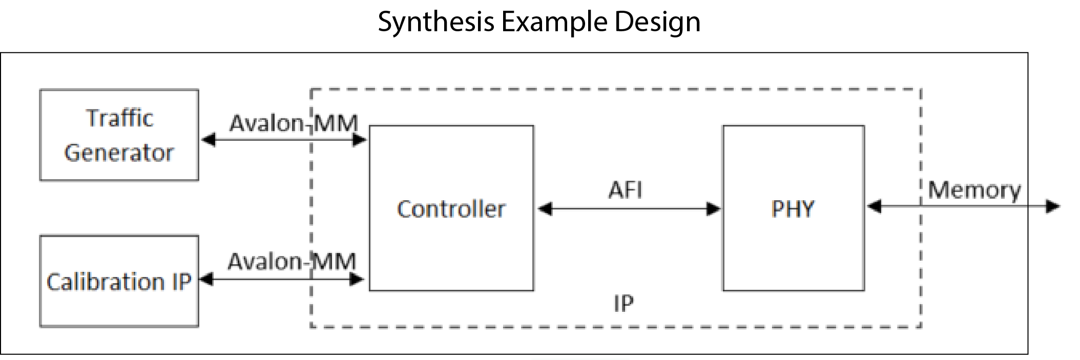
The synthesis design example contains the major blocks shown in the figure below.
- A traffic generator, which is a synthesizable Avalon® -MM example driver that implements a pseudo-random pattern of reads and writes to a parameterized number of addresses. The traffic generator also monitors the data read from the memory to ensure it matches the written data and asserts a failure otherwise.
- An instance of the memory interface, which includes:
- A memory controller that moderates between the Avalon® -MM interface and the AFI interface.
- The PHY, which serves as an interface between the memory controller and external memory devices to perform read and write operations.
Figure 7. Synthesis Design Example
Note: If one or more of the PLL Sharing Mode, DLL Sharing Mode, or OCT Sharing Mode parameters are set to any value other than No Sharing, the synthesis design example will contain two traffic generator/memory interface instances. The two traffic generator/memory interface instances are related only by shared PLL/DLL/OCT connections as defined by the parameter settings. The traffic generator/memory interface instances demonstrate how you can make such connections in your own designs.