2.3. Generating the Synthesizable EMIF Design Example
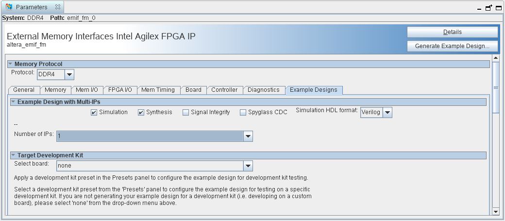
- On the Example Designs tab, ensure that the Synthesis box is checked.
- If you are implementing single interface example design, configure the EMIF IP and click File➤ Save to save the current setting into the user IP variation file (<user instance name>.ip).
Figure 2.
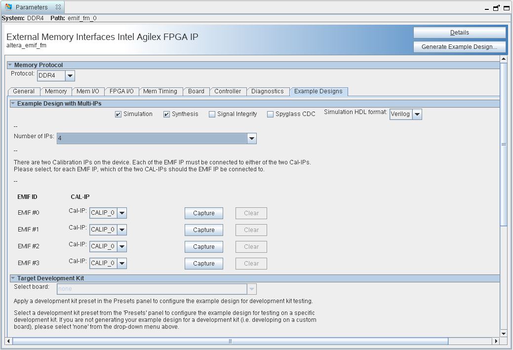
- If you are implementing an example design with multiple interfaces, specify Number of IPs to the desired number of interfaces. You can see the total number of EMIF ID same as the selected Number of IPs. Follow these steps to configure each interface:
- Select the Cal-IP to specify the connection of the interface to the Calibration IP.
- Configure the EMIF IP accordingly in all the Parameter Editor Tab.
- Return to Example Design tab and click Capture on the desired EMIF ID.
- Repeat step a to c for all EMIF ID.
- You may click the Clear button to remove the captured parameters and repeat step a to c to make changes to the EMIF IP.
- Click File➤ Save to save the current setting into the user IP variation file (<user instance name>.ip).
Figure 3.
- If you are implementing single interface example design, configure the EMIF IP and click File➤ Save to save the current setting into the user IP variation file (<user instance name>.ip).
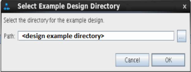
- Click Generate Example Design in the upper-right corner of the window.

- Specify a directory for the EMIF design example and click OK. Successful generation of the EMIF design example creates the following fileset under a qii directory.
- To open the example design, click , and navigate to the <project_directory>/<design_example_name>/qii/ed_synth.qpf and click Open.
Note: For information on compiling and programming the design example, refer to Compiling and Programming the Intel® Agilex™ EMIF Design Example.Figure 4. Generated Synthesizable Design Example File Structure

For information on constructing a system with two or more external memory interfaces, refer to Creating a Design Example with Multiple EMIF Interfaces, in the External Memory Interfaces Intel® Agilex™ FPGA IP User Guide.
For information on debugging multiple interfaces, refer to Enabling the EMIF Toolkit in an Existing Design, in the External Memory Interfaces Intel® Agilex™ FPGA IP User Guide.
If you don't select the Simulation or Synthesis checkbox, the destination directory contains only Platform Designer design files, which are not compilable by the Intel® Quartus® Prime software directly, but which you can view or edit in the Platform Designer. In this situation you can run the following commands to generate synthesis and simulation file sets.
- To create a compilable project, you must run the
script in the destination directory.quartus_sh -t make_qii_design.tcl - To create a simulation project, you must run the
script in the destination directory.quartus_sh -t make_sim_design.tcl