Quartus® Prime Pro Edition User Guide: Design Constraints
A newer version of this document is available. Customers should click here to go to the newest version.
2.1.4.8. Report NoC Performance
For designs that include the Hard Memory NoC, you can interactively generate a NoC Performance Report in Interface Planner.
The NoC Performance Report generation performs a static analysis of the NoC initiator and target locations to evaluate whether the placement allows your design to meet the bandwidth requirements and transaction sizes that you specify in the NoC Assignment Editor. You can review the report, and then make changes in the Plan tab based on the results.
To access the NoC Performance Report in Interface Planner, click the Reports tab, and then double-click Report NoC Performance in the Tasks pane.
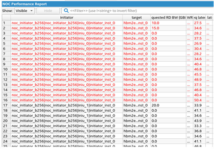
The NoC Performance Report reports performance data for each initiator to target connection. The latencies in this report are based on the minimum structural latency with respect to the initiator and target placement. These latencies are for the NoC portion of the path only. These latencies do not include any latency of, for instance, external memory access. Nor do these latencies account for potential delay due to congestion on the NoC. You can achieve lower minimum structural latency by placing the NoC initiators and targets closer together.
| NoC Performance Report Column | Description |
|---|---|
| Requested RD BW | The requested read bandwidth. |
| Requested WR BW | The requested write bandwidth. |
| NoC Req latency | The requested request latency. |
| NoC Res latency | The requested response latency. |
| Initiator placement | The placement location of the initiator element. |
| Target placement | The placement location of the target element. |
| Message | Text message that identifies the reason that the current placement cannot meet the requested bandwidth. |
One possible reason the Message reports that the current placement cannot meet the requested bandwidth is because of over-saturation of an initiator or a target. For example, if the sum of all bandwidth requirements through a particular initiator is greater than the bandwidth that the initiator can support, based on the data width and operating frequency of its AXI4 interface. To avoid this problem, either reduce bandwidth requirements or increase bandwidth capability.
Another possible reason that the current placement cannot meet the requested bandwidth is over-saturation of the horizontal bandwidth available in the NoC. This condition is the result of multiple initiator to target connections requesting bandwidth in the same direction through a horizontal section of the NoC. The NoC Performance Report message reports the congested segments. You can adjust initiator placement to alleviate congestion.
You can also view NoC elements in the Quartus® Prime Chip Planner, and view connectivity of NoC elements in following fitting in the NoC Connectivity Report, as the Agilex® 7 M-Series FPGA Network-on-Chip (NoC) User Guide.