3.2.1.1. IP Tab Options
On the IP tab, specify the parameters to configure the MIPI and video interface for your IP.
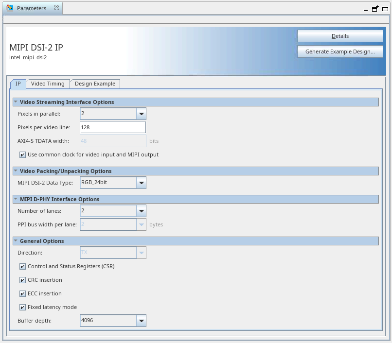
Figure 7. IP Tab Parameters
| Parameter | Range Selection | Default Setting | Description |
|---|---|---|---|
| Pixels in parallel | 1, 2, 4 | 2 | Select the number of pixels presented on each beat of the input video interface. |
| Pixels per video line | 1–8192 | 128 | Indicate the number of pixels on a video line. This must be set to the exact line length to be transmitted. |
| Use common clock for video input and MIPI output | On/Off | On | When the common clock is enabled, the video input must be driven from the MIPI link clock for this interface. This allows the MIPI DSI-2 IP to operate with a single clock domain and enables the fixed latency mode option. |
| AXI4-S TDATA width | 1–96 | N/A | This parameter indicates the calculated width of the video TDATA input based on the IP configuration. This value is fixed and cannot be changed. |
| MIPI DSI-2 data type |
|
RGB 24bit | Select the MIPI DSI-2 data type to be used when video data is packed into MIPI DSI-2 packets. The pixel data received on the AXI4-Stream interface must correspond to this data type. |
| Number of lanes | 1, 2, 4 | 2 | MIPI lanes on the external MIPI D-PHY interface. This must correspond to the MIPI D-PHY IP configuration. |
| PPI bus width | 2 | 2 | This indicates the number of bytes per lane on the data interface on the PPI. This value is fixed and cannot be changed. |
| Direction | Tx | Tx | This option is fixed to TX. The IP is currently only available as a transmitter. |
| Control and Status Registers (CSRs) | On/Off | On | When Control and Status Registers are off, the control and status register interface is not included. Disabling this option reduces the IP resource utilization but the CVO and Video Timing Generator cannot be dynamically reconfigured. |
| CRC insertion | On/Off | On | Cyclic redundancy check (CRC) processing. When CRC insertion is disabled, the IP does not calculate long packet payload CRC and it sets the fixed value zero in the checksum field. Disabling this parameter reduces the resource utilization in your system architecture where it is not required.
Note: If you choose to disable CRC insertion for your system, the output from the IP will not comply with the MIPI DSI-2 specification.
|
| ECC insertion | On/Off | On | Error correction code (ECC) processing. When ECC insertion is disabled, the IP does not calculate the header ECC code and sets the fixed value zero in the ECC field in all packet headers. Disabling this parameter reduces the resource utilization in your system architecture where it is not required.
Note: If you choose to disable ECC insertion for your system, the output from the IP will not comply with the MIPI DSI-2 specification.
|
| Fixed latency mode | On/Off | On | The fixed latency mode adheres strictly to the video timing configured in the IP. When disabled, the video is passed with minimum latency. So, the MIPI output follows the line and frame intervals configured. The sync locations may vary slightly within lines, depending on the timing configured. Enabling this option slightly increases logic and memory utilisation.
Note: Only use this option when common video input and MIPI clocks are enabled.
|
| Buffer depth | 128– 65536 | 4096 | Configure the internal data buffer depth. This must be enough to hold at least 1.2 video lines. If the incoming video data is very bursty, increasing this option enhances resilience to data underflow errors within the IP. To assist you in selecting the appropriate buffer size, the currently selected buffer depth is translated into video lines and displayed by the IP. It also can be calculated using this formula:
|