External Memory Interfaces (EMIF) IP User Guide: Agilex™ 3 FPGAs and SoCs
A newer version of this document is available. Customers should click here to go to the newest version.
3.2. Generating and Configuring the EMIF IP
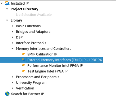
- In the IP Catalog window, select External Memory Interfaces IP. (If the IP Catalog window is not visible, select View > IP Catalog.)
Figure 4. IP Catalog
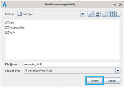
- In the IP Parameter Editor, provide an entity name for the EMIF IP (the name that you provide here becomes the file name for the IP) and specify a directory. Click Create.
Figure 5. Specifying a File name
- The parameter editor has multiple tabs where you must configure parameters to reflect your EMIF implementation.
- The following table provides high-level guidance for parameterizing the tabs in the Agilex™ 3 EMIF IP parameter editor.
Parameter Editor Tab Guidelines High Level Configuration: Memory Device Ensure that you correctly enter the following parameters under the Memory Device section:
- Number of Channels
- Data DQ Width
- Die Density
- CS (Chip Select) Width
- Memory Operating Frequency
High Level Configuration: PHY The parameters in the PHY section allow you to set the following values:
- Reference clock frequency.
- AC placement.
- Pin swizzle map.
- Use Debug Toolkit.
In addition, you can select the desired mode from Mainband Access Mode, to connect the EMIF IP to user logic:
- Sunchronous fabric.
- Asynchronous fabric.
High Level Configuration: Controller Set the controller Options section according to the desired configuration and behavior for your memory controller:
- In-line ECC
- Data masking
- WDBI
- RDBI
Advanced: Memory Timing Allows you to modify timing parameter settings.
Advanced: Analog Overrides Allows you to modify the termination, drive strength, and VREF settings.
Example Design: Fileset Type and User PLL The Example Design tab lets you select which HDL to use for the top-level files, and which file sets you want the design example to generate:
- Synthesis
- Simulation
- Core clock frequency
- Core reference frequency
You should make these selections before clicking Generate Example Design.... The generated design example is a complete EMIF system consisting of the EMIF IP and a driver to validate the memory interface.
Example Design: Performance Monitor Enable performance monitor on all channels for measuring read/write transaction metrics.
Example Design: Traffic Generator Allows you to specify the traffic pattern that you want to run, as follows:
- Short mode
- Medium mode
- Long mode
- Infinite mode