AN 1000: Drive-on-Chip Design Example: Agilex™ 5 Devices
ID
826207
Date
7/08/2024
Public
1. About the Drive-on-Chip Design Example for Agilex™ 5 Devices
2. Features of the Drive-on-Chip Design Example for Agilex Devices
3. Getting Started with the Drive-on-Chip Design Example
4. Rebuilding the Drive-on-Chip Design Example
5. Modifying the Design Example for a Different Board
6. About the Scaling of Feedback Signals
7. Motor Control Software
8. Functional Description of the Drive-on-Chip Design Example for Agilex 5 Devices
9. Signals
10. Registers
11. Design Security Recommendations
12. Document Revision History for AN 1000: Drive-on-Chip Design Example for Agilex™ 5 Devices
3.1. Software Requirements for the Drive-on-Chip Design Example for Agilex 5 Devices
3.2. Hardware Requirements for the Drive-on-Chip Design Example for Agilex 5 Devices
3.3. Downloading and Installing the Design
3.4. Setting Up your Development Board for the Drive-on-Chip Design Example for Agilex 5 Devices
3.5. Configuring the FPGA Hardware for the Drive-on-Chip Design Example for Agilex 5 Devices
3.6. Programming the Nios V/g Software to the Device for the Drive-on-Chip Design Example for Agilex Devices
3.7. Debugging and Monitoring the Drive-on-Chip Design Example for Agilex 5 Devices with Python GUI
8.3.6.1. DSP Builder Model for the Drive-on-Chip Designs
8.3.6.2. Avalon Memory-Mapped Interface
8.3.6.3. About DSP Builder for Intel FPGAs
8.3.6.4. DSP Builder for Intel FPGAs Folding
8.3.6.5. DSP Builder for Intel FPGAs Design Guidelines
8.3.6.6. Generating VHDL for the DSP Builder Models for the Drive-on-Chip Designs
8. Functional Description of the Drive-on-Chip Design Example for Agilex 5 Devices
The design consists of two main elements: Platform Designer, DSP Builder for Intel FPGAs, IP, and RTL sources compiled into an FPGA programming file; and C source code compiled to run on an Nios V/g processor in the FPGA.
The Platform Designer system consists of:
- Nios V/g processor subsystem.
- One or two motor drive axes comprising the following motor control peripheral components:
- 6-channel PWM
- Drive system monitor
- Quadrature encoder interface
- Resolver SPI interface
- ADC interface
- Motor and power board model subsystem.
Figure 22. Platform Designer Top-Level Design
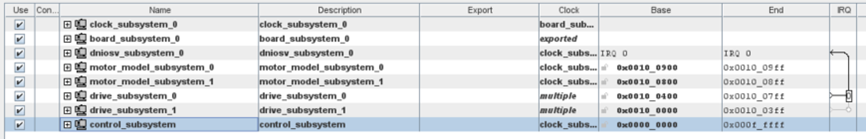
Figure 23. Platform Designer Nios V processor Subsystem
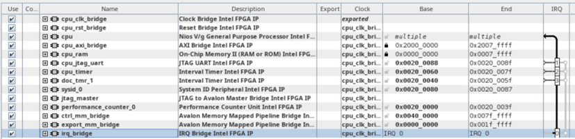
Figure 24. Platform Designer Clock Subsystem
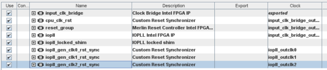
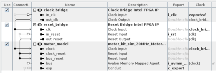
Figure 25. Platform Designer drive Subsystem
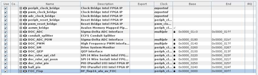
Figure 26. Platform Designer Control Subsystem
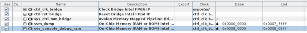
Figure 27. Platform Designer Motor Model Subsystem