AN 841: Signal Tap Tutorial for Intel® Stratix® 10 Partial Reconfiguration Design
ID
683875
Date
1/28/2022
Public
2.1. Step 1: Getting Started
2.2. Step 2: Preparing the Base Revision
2.3. Step 3: Preparing the Implementation Revisions for Debugging
2.4. Step 4: Configuring Signal Tap Logic Analyzer
2.5. Step 5: Generating Programming Files
2.6. Step 6: Programming the FPGA Device
2.7. Step 7: Performing Data Acquisition
2.2.1. Preparing the Static Region
- Ensure that blinking_led is the current revision.
To change the revision to the blinking_led revision, click Project > Revisions and set blinking_led as the current revision.
- Add the SLD JTAG Bridge Agent Intel® FPGA IP to the design:
- In the IP Catalog (Tools > IP Catalog), type SLD JTAG Bridge Agent, and double-click the SLD JTAG Bridge Agent Intel® FPGA IP .
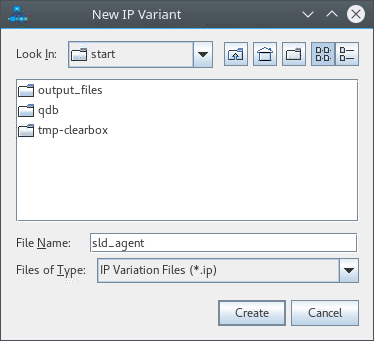
- In the New IP Variant dialog box, type sld_agent as the file name, and then click Create.
Figure 4. New IP Variant Dialog Box
- In the parameter editor, use the default parameterization for sld_agent. Click Generate HDL and then click Generate.
Save your changes, if prompted.
Figure 5. SLD JTAG Bridge Agent Intel® FPGA IP Parameters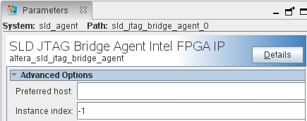 The parameter editor generates the sld_agent.ip IP variation file and adds the file to the blinking_led project.
 - Close the parameter editor.
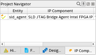
- Verify whether the sld_agent IP variant appears in the IP Components tab of the Project Navigator.
Figure 6. sld_agent IP Variant in Project NavigatorIf the IP variant does not appear in the Project Navigator, click Project > Add/Remove Files in Project, find the sld_agent.ip file, and add to the project.
- In the top.sv file, instantiate the sld_agent IP in the base revision by uncommenting the following block of code:
//==============
//Uncomment this block to enable Signal Tap

wire tck;
wire tms;
wire tdi;
wire vir_tdi;
wire ena;
wire tdo;

sld_agent u_sld_agent (
 .tck  (tck),  //  output,  width = 1, connect_to_bridge_host.tck
 .tms  (tms),  //  output,  width = 1, .tms
 .tdi  (tdi),  //  output,  width = 1, .tdi
 .vir_tdi (vir_tdi), //  output,  width = 1, .vir_tdi
 .ena  (ena),  //  output,  width = 1,  .ena
 .tdo  (tdo)   //  input,   width = 1,  .tdo
);

//==============
- Add the Reset Release Intel FPGA IP to the design:
- In the IP Catalog (Tools > IP Catalog), type Reset Release, and double-click the Reset Release Intel FPGA IP.
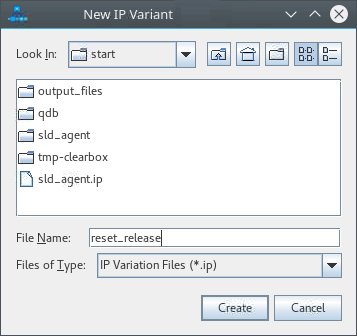
- In the New IP Variant dialog box, type reset_release as the file name, and then click Create.
Figure 7. New IP Variant Dialog Box
- In the parameter editor, under Type of reset output port, select Conduit Interface. Click Generate HDL and then click Generate.
Save your changes, if prompted.
Figure 8. Reset Release Intel FPGA IP Parameters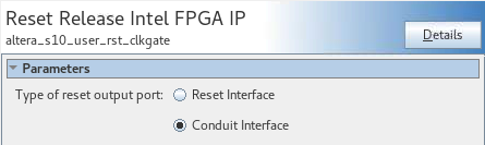 The parameter editor generates the reset_release.ip IP variation file and adds the file to the blinking_led project.
 - Close the parameter editor.
- Verify whether the reset_release IP variant appears in the IP Components tab of the Project Navigator.
Figure 9. reset_release IP Variant in Project Navigator
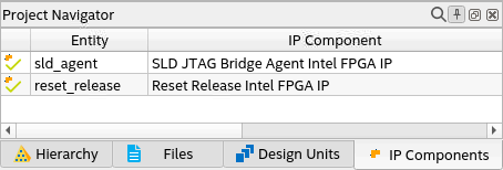 If the IP variant does not appear in the Project Navigator, click Project > Add/Remove Files in Project, find the reset.ip file, and add it to the project.
 - In the blinking_led.sv file, instantiate the reset_release IP in the default persona by uncommenting the following block of code:
//==============
//Uncomment this block to enable Signal Tap

wire connect_to_conf_rst;

reset_release u_reset_release (ninit_done (connect_to_conf_rst)  //  output,  width = 1, ninit_done.ninit_done
 );

//==============