A newer version of this document is available. Customers should click here to go to the newest version.
12.1. F-Tile DisplayPort PHY FPGA IP Parameters
| Parameter | Values | Default | Description |
|---|---|---|---|
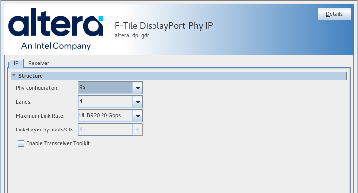
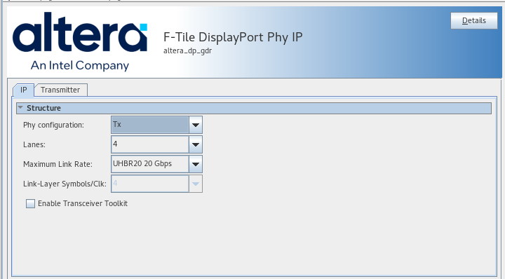
| Phy configuration | Tx Rx |
Rx | Selects the PHY configuration as either Rx or Tx. |
| Lanes | 1, 2, or 4 |
4 | The DisplayPort protocol supports 1,2 or 4 lanes. This configuration allocates 1,2 or 4 transceiver channels and adjusts the interface width between the PHY and protocol IP. Ensure the PHY and protocol core lane settings are the same as mismatches cause malfunctions. You cannot automatically detect this issue in your design. |
| Maximum Link Rate |
|
UHBR10 10Gbps | The altera_dp IP includes a maximum line rate selector that requires adjustment to align with the specified value. When you set this value, the width of the interface signals passing between the PHY and protocol core changes. If the PHY and protocol IP link rate settings do not match, the solution does not work correctly. You cannot automatically detect this issue in your design. |
| Link-Layer Symbols/Clk | 4 | 4 | Defines the number of link-layer symbols transferred with each clock. |
| Enable Transceiver Toolkit | On or Off | Off | When on, this allows access to debug functions such as eye capture and manual analog parameter settings in the F-tile transceiver, via the Transceiver Toolkit debug environment. |
| Parameter | Values | Default | Description |
|---|---|---|---|
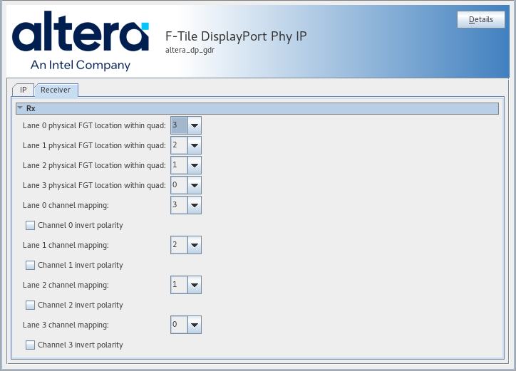
| Lane 0 physical FGT location in quad | 0,1,2,3 | 3 | Defines the physical location of lane 0 in the transceiver quad. In most cases, you need not change the parameter from the default. (Rx only) |
| Lane 1 physical FGT location in quad | 0,1,2,3 | 2 | Defines the physical location of lane 1 in the transceiver quad. In most cases, you need not change the parameter from the default. (Rx only) |
| Lane 2 physical FGT location in quad | 0,1,2,3 | 1 | Defines the physical location of lane 2 in the transceiver quad. In most cases, you need not change the parameter from the default. (Rx only) |
| Lane 3 physical FGT location in quad | 0,1,2,3 | 0 | Defines the physical location of lane 3 in the transceiver quad. In most cases, you need not change the parameter from the default. (Rx only) |
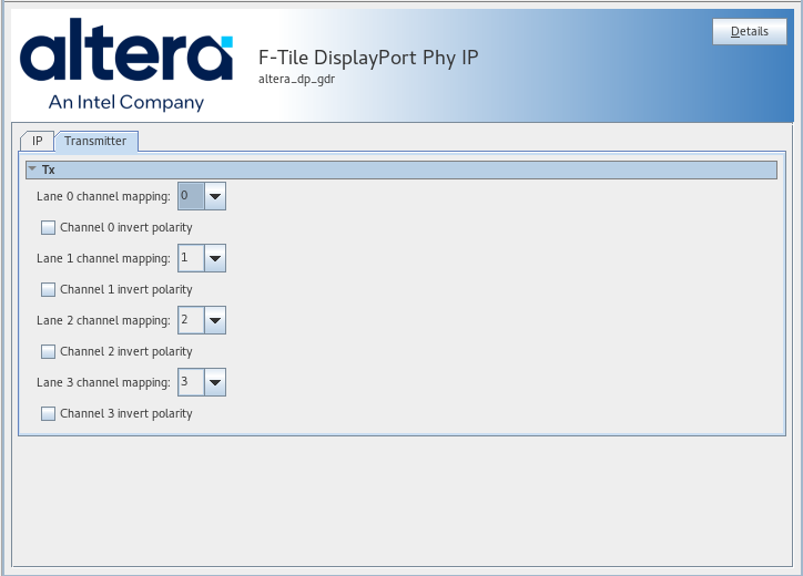
| Channel 0 invert polarity | On or off. | Off | Inverts the output polarity of channel 0 |
| Channel 1 invert polarity | On or off. | Off | Inverts the output polarity of channel 1 |
| Channel 2 invert polarity | On or off. | Off | Inverts the output polarity of channel 2 |
| Channel 3 invert polarity | On or off. | Off | Inverts the output polarity of channel 3 |
| Lane 0 Channel Mapping | 0,1,2,3 | 0 | Defines the transceiver channel DisplayPort Lane 0 is mapped to. This parameter depends on the FMC or PCB you are using in your design. |
| Lane 1 Channel Mapping | 0,1,2,3 | 1 | Defines the transceiver channel DisplayPort Lane 1 is mapped to. This parameter depends on the FMC or PCB you are using in your design. |
| Lane 2 Channel Mapping | 0,1,2,3 | 2 | Defines the transceiver channel DisplayPort Lane 2 is mapped to. This parameter dependd on the FMC or PCB you are using in your design. |
| Lane 3 Channel Mapping | 0,1,2,3 | 3 | Defines the transceiver channel DisplayPort Lane 3 is mapped to. This parameter depends on the FMC or PCB you are using in your design. |