A newer version of this document is available. Customers should click here to go to the newest version.
1. DisplayPort IP Quick Reference
2. About The DisplayPort IP
3. Getting Started
4. DisplayPort IP Hardware Design Examples
5. DisplayPort Source
6. DisplayPort Sink
7. DisplayPort IP Parameters
8. DisplayPort IP Simulation Example
9. DisplayPort API Reference
10. DisplayPort Source Register Map and DPCD Locations
11. DisplayPort Sink Register Map and DPCD Locations
12. F-Tile DisplayPort PHY FPGA IP
13. GTS DisplayPort PHY IP ( Agilex™ 5 Designs Only)
14. Duplex and Dual Simplex PHY Modes ( Agilex™ 5 Designs Only)
15. DisplayPort IP User Guide Archives
16. Document Revision History for the DisplayPort IP User Guide
4.1. DisplayPort IP Hardware Design Examples for Arria® 10, Cyclone® 10 GX, Stratix® 10, Agilex™ 7 F-Tile, and Agilex™ 5 E-Series (GTS) Devices
4.2. HDCP Over DisplayPort Design Example for Arria® 10 and Stratix® 10 Devices
4.3. DisplayPort IP Hardware Design Examples for Arria V, Cyclone V, and Stratix V Devices
4.3.1. Clock Recovery Core
4.3.2. Transceiver and Clocking
4.3.3. Required Hardware
4.3.4. Design Walkthrough
4.3.5. DisplayPort Link Training Flow
4.3.6. DisplayPort Post Link Training Adjust Request Flow (LQA)
4.3.7. Translating DisplayPort Link Training AUX Transactions
4.3.8. DisplayPort MST Source User Application
6.6.1. Controller Interface
6.6.2. AUX Interface
6.6.3. Debugging Interface
6.6.4. Video Interface
6.6.5. Video Interface (Enable Active Video Data Protocols = AXIS-VVP Full)
6.6.6. Clocked Video Input Interface
6.6.7. RX Transceiver Interface
6.6.8. Transceiver Reconfiguration Interface
6.6.9. Secondary Stream Interface
6.6.10. Audio Interface
6.6.11. Non-GPU Mode EDID Interface
6.6.12. MSA Interface
9.1. Using the Library
9.2. btc_dprx_syslib API Reference
9.3. btc_dprx_aux_get_request
9.4. btc_dprx_aux_handler
9.5. btc_dprx_aux_post_reply
9.6. btc_dprx_baseaddr
9.7. btc_dprx_dpcd_gpu_access
9.8. btc_dprx_edid_set
9.9. btc_dprx_hpd_get
9.10. btc_dprx_hpd_pulse
9.11. btc_dprx_hpd_set
9.12. btc_dprx_lt_eyeq_init
9.13. btc_dprx_lt_force
9.14. btc_dprx_lt_ffe_retries_set
9.15. btc_dprx_lt_ffe_default_set
9.16. btc_dprx_rtl_ver
9.17. btc_dprx_sw_ver
9.18. btc_dprx_syslib_add_rx
9.19. btc_dprx_syslib_info
9.20. btc_dprx_syslib_init
9.21. btc_dprx_syslib_monitor
9.22. btc_dprx_mst_link_addr_rep_set
9.23. btc_dprx_mst_conn_stat_notify_req
9.24. btc_dprx_mst_conn_stat_notify_rep
9.25. btc_dptx_syslib API Reference
9.26. btc_dptx_aux_i2c_read
9.27. btc_dptx_aux_i2c_write
9.28. btc_dptx_aux_read
9.29. btc_dptx_aux_write
9.30. btc_dptx_aux_set_read_reply_timeout
9.31. btc_dptx_aux_set_max_num_defers
9.32. btc_dptx_baseaddr
9.33. btc_dptx_edid_block_read
9.34. btc_dptx_edid_read
9.35. btc_dptx_fast_link_training
9.36. btc_dptx_hpd_change
9.37. btc_dptx_is_link_up
9.38. btc_dptx_link_bw
9.39. btc_dptx_link_training
9.40. btc_dptx_link_training_with_retries
9.41. btc_dptx_set_128b132b_lt_400ms_timeout
9.42. btc_dptx_get_lt_failure_count
9.43. btc_dptx_reset_lt_failure_counters
9.44. btc_dptx_rtl_ver
9.45. btc_dptx_set_color_space
9.46. btc_dptx_sw_ver
9.47. btc_dptx_syslib_add_tx
9.48. btc_dptx_syslib_init
9.49. btc_dptx_syslib_monitor
9.50. btc_dptx_test_autom
9.51. btc_dptx_video_enable
9.52. btc_dptx_mst_allocate_payload_rep
9.53. btc_dptx_mst_allocate_payload_req
9.54. btc_dptx_mst_clear_payload_table_rep
9.55. btc_dptx_mst_clear_payload_table_req
9.56. btc_dptx_mst_conn_stat_notify_req
9.57. btc_dptx_mst_down_rep_irq
9.58. btc_dptx_mst_enable
9.59. btc_dptx_mst_enum_path_rep
9.60. btc_dptx_mst_enum_path_req
9.61. btc_dptx_mst_get_msg_transact_ver_rep
9.62. btc_dptx_mst_get_msg_transact_ver_req
9.63. btc_dptx_mst_link_address_rep
9.64. btc_dptx_mst_link_address_req
9.65. btc_dptx_mst_remote_dpcd_wr_rep
9.66. btc_dptx_mst_remote_dpcd_wr_req
9.67. btc_dptx_mst_remote_i2c_rd_rep
9.68. btc_dptx_mst_remote_i2c_rd_req
9.69. btc_dptx_mst_set_color_space
9.70. btc_dptx_mst_tavgts_set
9.71. btc_dptx_mst_up_req_irq
9.72. btc_dptx_mst_vcpid_set
9.73. btc_dptx_mst_vcptab_addvc
9.74. btc_dptx_mst_vcptab_clear
9.75. btc_dptx_mst_vcptab_delvc
9.76. btc_dptx_mst_vcptab_update
9.77. btc_dptxll_syslib API Reference
9.78. btc_dptxll_hpd_change
9.79. btc_dptxll_hpd_irq
9.80. btc_dptxll_mst_cmp_ports
9.81. btc_dptxll_mst_edid_read_rep
9.82. btc_dptxll_mst_edid_read_req
9.83. btc_dptxll_mst_get_device_ports
9.84. btc_dptxll_mst_set_csn_callback
9.85. btc_dptxll_mst_topology_discover
9.86. btc_dptxll_stream_allocate_rep
9.87. btc_dptxll_stream_allocate_req
9.88. btc_dptxll_stream_calc_VCP_size
9.89. btc_dptxll_stream_delete_rep
9.90. btc_dptxll_stream_delete_req
9.91. btc_dptxll_stream_get
9.92. btc_dptxll_stream_set_color_space
9.93. btc_dptxll_stream_set_pixel_rate
9.94. btc_dptxll_sw_ver
9.95. btc_dptxll_syslib_set_max_num_lt_retries
9.96. btc_dptxll_syslib_get_max_num_lt_retries
9.97. btc_dptxll_syslib_add_tx
9.98. btc_dptxll_syslib_init
9.99. btc_dptxll_syslib_monitor
9.100. btc_dpxx_syslib Additional Types
9.101. btc_dprx_syslib Supported DPCD Locations
10.1. Source General Registers
10.2. Source MSA Registers
10.3. Source Link PHY Control and Status
10.4. Source Timestamp
10.5. Source CRC Registers
10.6. Source Audio Registers
10.7. Source MST Registers
10.8. Source AUX Controller Interface
10.9. Source-Supported DPCD Locations
10.10. Source AXI2CV Registers
10.2.1. DPTX0_MSA_MVID
10.2.2. DPTX0_MSA_NVID
10.2.3. DPTX0_MSA_HTOTAL
10.2.4. DPTX0_MSA_VTOTAL
10.2.5. DPTX0_MSA_HSP
10.2.6. DPTX0_MSA_HSW
10.2.7. DPTX0_MSA_HSTART
10.2.8. DPTX0_MSA_VSTART
10.2.9. DPTX0_MSA_VSP
10.2.10. DPTX0_MSA_VSW
10.2.11. DPTX0_MSA_HWIDTH
10.2.12. DPTX0_MSA_VHEIGHT
10.2.13. DPTX0_MSA_MISC0
10.2.14. DPTX0_MSA_MISC1
10.2.15. DPTX0_MSA_COLOR
10.2.16. DPTX0_VBID
10.3.1. DPTX_PRE_VOLT0/DPTX_REG_TXFFE0
10.3.2. DPTX_PRE_VOLT1/DPTX_REG_TXFFE1
10.3.3. DPTX_PRE_VOLT2/DPTX_REG_TXFFE2
10.3.4. DPTX_PRE_VOLT3/DPTX_REG_TXFFE3
10.3.5. DPTX_RECONFIG
10.3.6. DPTX_TEST_80BIT_PATTERN1/DPTX_TEST_264BIT_PATTERN1
10.3.7. DPTX_TEST_80BIT_PATTERN2/DPTX_TEST_264BIT_PATTERN2
10.3.8. DPTX_TEST_80BIT_PATTERN3/DPTX_TEST_264BIT_PATTERN3
10.3.9. DPTX_TEST_264BIT_PATTERN4
10.3.10. DPTX_TEST_264BIT_PATTERN5
10.3.11. DPTX_TEST_264BIT_PATTERN6
10.3.12. DPTX_TEST_264BIT_PATTERN7
10.3.13. DPTX_TEST_264BIT_PATTERN8
10.3.14. DPTX_TEST_264BIT_PATTERN9
10.8.1. DPTX_AUX_CONTROL
10.8.2. DPTX_AUX_COMMAND
10.8.3. DPTX_AUX_BYTE0
10.8.4. DPTX_AUX_BYTE1
10.8.5. DPTX_AUX_BYTE2
10.8.6. DPTX_AUX_BYTE3
10.8.7. DPTX_AUX_BYTE4
10.8.8. DPTX_AUX_BYTE5
10.8.9. DPTX_AUX_BYTE6
10.8.10. DPTX_AUX_BYTE7
10.8.11. DPTX_AUX_BYTE8
10.8.12. DPTX_AUX_BYTE9
10.8.13. DPTX_AUX_BYTE10
10.8.14. DPTX_AUX_BYTE11
10.8.15. DPTX_AUX_BYTE12
10.8.16. DPTX_AUX_BYTE13
10.8.17. DPTX_AUX_BYTE14
10.8.18. DPTX_AUX_BYTE15
10.8.19. DPTX_AUX_BYTE16
10.8.20. DPTX_AUX_BYTE17
10.8.21. DPTX_AUX_BYTE18
10.8.22. DPTX_AUX_RESET
10.10.2.1. STATUS (0x50)
10.10.2.2. VIDEO_MODE_MATCH (0X51)
10.10.2.3. VIDEO_MODE_BANK_SELECT (0x53)
10.10.2.4. VIDEO_MODE_CONTROL (0x54)
10.10.2.5. VIDEO_MODE_SAMPLE_COUNT(0x55)
10.10.2.6. VIDEO_MODE_F0_LINE_COUNT (0x56)
10.10.2.7. VIDEO_MODE_F1_LINE_COUNT (0x57)
10.10.2.8. VIDEO_MODE_HORIZONTAL_FRONT_PORCH (0x58)
10.10.2.9. VIDEO_MODE_HORIZONTAL_SYNC_LENGTH (0x59)
10.10.2.10. VIDEO_MODE_HORIZONTAL_BLANKING (0x5A)
10.10.2.11. VIDEO_MODE_VERTICAL_FRONT_PORCH (0x5B)
10.10.2.12. VIDEO_MODE_VERTICAL_SYNC_LENGTH (0x5C)
10.10.2.13. VIDEO_MODE_VERTICAL_BLANKING (0x5D)
10.10.2.14. VIDEO_MODE_F0_VERTICAL_FRONT_PORCH (0x5E)
10.10.2.15. VIDEO_MODE_F0_VERTICAL_SYNC_LENGTH (0x5F)
10.10.2.16. VIDEO_MODE_F0_VERTICAL_BLANKING (0x60)
10.10.2.17. VIDEO_MODE_ACTIVE_PICTURE_LINE (0x61)
10.10.2.18. VIDEO_MODE_F0_VERTICAL_RISING (0x62)
10.10.2.19. VIDEO_MODE_FIELD_RISING (0x63)
10.10.2.20. VIDEO_MODE_FIELD_FALLING (0x64)
10.10.2.21. VIDEO_MODE_VALID (0x6D)
11.1. Sink General Registers
11.2. Sink Timestamp
11.3. Sink Bit-Error Counters
11.4. FEC Registers
11.5. 128B/132B Link Quality Test Pattern Registers
11.6. Sink MSA Registers
11.7. Sink Audio Registers
11.8. Sink MST Registers
11.9. Sink AUX Controller Interface
11.10. Sink CRC Registers
11.11. Sink-Supported DPCD Locations
11.12. Sink CV2AXI Registers
11.6.1. DPRX0_MSA_MVID
11.6.2. DPRX0_MSA_NVID
11.6.3. DPRX0_MSA_HTOTAL
11.6.4. DPRX0_MSA_VTOTAL
11.6.5. DPRX0_MSA_HSP
11.6.6. DPRX0_MSA_HSW
11.6.7. DPRX0_MSA_HSTART
11.6.8. DPRX0_MSA_VSTART
11.6.9. DPRX0_MSA_VSP
11.6.10. DPRX0_MSA_VSW
11.6.11. DPRX0_MSA_HWIDTH
11.6.12. DPRX0_MSA_VHEIGHT
11.6.13. DPRX0_MSA_MISC0
11.6.14. DPRX0_MSA_MISC1
11.6.15. DPRX0_MSA_COLOR
11.6.16. DPRX0_VBID
11.9.1. DPRX_AUX_CONTROL
11.9.2. DPRX_AUX_STATUS
11.9.3. DPRX_AUX_COMMAND
11.9.4. DPRX_AUX_BYTE0
11.9.5. DPRX_AUX_BYTE1
11.9.6. DPRX_AUX_BYTE2
11.9.7. DPRX_AUX_BYTE3
11.9.8. DPRX_AUX_BYTE4
11.9.9. DPRX_AUX_BYTE5
11.9.10. DPRX_AUX_BYTE6
11.9.11. DPRX_AUX_BYTE7
11.9.12. DPRX_AUX_BYTE8
11.9.13. DPRX_AUX_BYTE9
11.9.14. DPRX_AUX_BYTE10
11.9.15. DPRX_AUX_BYTE11
11.9.16. DPRX_AUX_BYTE12
11.9.17. DPRX_AUX_BYTE13
11.9.18. DPRX_AUX_BYTE14
11.9.19. DPRX_AUX_BYTE15
11.9.20. DPRX_AUX_BYTE16
11.9.21. DPRX_AUX_BYTE17
11.9.22. DPRX_AUX_BYTE18
11.9.23. DPRX_AUX_I2C0
11.9.24. DPRX_AUX_I2C1
11.9.25. DPRX_AUX_RESET
11.9.26. DPRX_AUX_HPD
11.12.2.1. STATUS (0x50)
11.12.2.2. ACTIVE SAMPLE COUNT (0x52)
11.12.2.3. F0_ACTIVE_LINE_COUNT (0x53)
11.12.2.4. F1_ACTIVE_LINE_COUNT (0x54)
11.12.2.5. TOTAL_SAMPLE_COUNT (0x55)
11.12.2.6. F0_TOTAL_LINE_COUNT (0x56)
11.12.2.7. F1_TOTAL_LINE_COUNT (0x57)
11.12.2.8. COLOR_PATTERN (0x5C)
11.12.2.9. CONTROL (0x64)
13.2. DisplayPort Analog Parameters for GTS IPs ( Agilex™ 5 Designs Only)
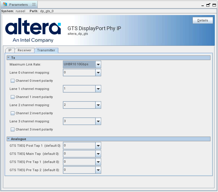
For Agilex™ 5 designs only, FMC boards and development kits have unique physical connections to serial lines, and this feature lets you configure these connections per lane in the GUI. You can choose your preferred connections per lane within the GUI. The GUI shows a default 1-1 mapping, but you can change this to match your needs. Be aware that the PHY assumes Transceiver Channel 0 carries DisplayPort Lane 0 by default, but your design may differ.
GTS DisplayPort PHY IP Parameter Editor Settings
Note: The configuration options in the IP parameter are identical for both the Transmitter and Receiver tabs, ensuring a consistent setup process. .
Figure 58. GTS Receiver and Transmitter Tab Options in Parameter Editor
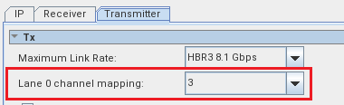
For example, if using Transceiver Lane 0 in the GTS, but your PCB layout may require that it carries data for DisplayPort Lane 3. In this scenario, adjust the values.
Figure 59. Lane 0 Channel Mapping
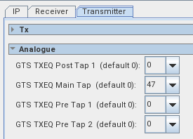
Transmitter Analog Settings
Based on your board specific features, you may have to change the TX analog parameters. You should test various values to achieve the lowest bit-error rate in your hardware testing.
Figure 60. GTS DisplayPort Analog Options in Parameter Editor
| Parameter | Values 5 | Description |
|---|---|---|
| GTS TX EQ Post Tap 1 (default 0) | 0 to 19 | TX equalization control for Post Tap 1. Default value is 0 6. |
| GTS TX EQ Main Tap (default 0) | 0 to 55 | TX equalization control for Main Tap. Default value is 0. |
| GTS TX EQ Pre Tap 1 (default 0) | 0 to 15 | TX equalization control for Pre Tap 1. Default value is 0. |
| GTS TX EQ Pre Tap 2 (default 0) | 0 to 7 | TX equalization control for Pre Tap 2. Default value is 0. |
5 For the Premium and Modular devkits, the GTS TX EQ MAIN Tap value must be set to 47
6 This is the default value but you can change this value in the Analog Parameter GUI