Intel® Quartus® Prime Pro Edition User Guide: Timing Analyzer
ID
683243
Date
8/03/2023
Public
A newer version of this document is available. Customers should click here to go to the newest version.
2.2.1. Timing Path and Clock Analysis
2.2.2. Clock Setup Analysis
2.2.3. Clock Hold Analysis
2.2.4. Recovery and Removal Analysis
2.2.5. Multicycle Path Analysis
2.2.6. Metastability Analysis
2.2.7. Timing Pessimism
2.2.8. Clock-As-Data Analysis
2.2.9. Multicorner Timing Analysis
2.2.10. Time Borrowing
3.1. Timing Analysis Flow
3.2. Step 1: Specify Timing Analyzer Settings
3.3. Step 2: Specify Timing Constraints
3.4. Step 3: Run the Timing Analyzer
3.5. Step 4: Analyze Timing Reports
3.6. Applying Timing Constraints
3.7. Timing Analyzer Tcl Commands
3.8. Timing Analysis of Imported Compilation Results
3.9. Using the Intel® Quartus® Prime Timing Analyzer Document Revision History
3.10. Intel® Quartus® Prime Pro Edition User Guide: Timing Analyzer Archive
3.5.1.1. Report Fmax Summary
3.5.1.2. Report Timing
3.5.1.3. Report Timing By Source Files
3.5.1.4. Report Data Delay
3.5.1.5. Report Net Delay
3.5.1.6. Report Clocks and Clock Network
3.5.1.7. Report Clock Transfers
3.5.1.8. Report Metastability
3.5.1.9. Report CDC Viewer
3.5.1.10. Report Asynchronous CDC
3.5.1.11. Report Logic Depth
3.5.1.12. Report Neighbor Paths
3.5.1.13. Report Register Spread
3.5.1.14. Report Route Net of Interest
3.5.1.15. Report Retiming Restrictions
3.5.1.16. Report Register Statistics
3.5.1.17. Report Pipelining Information
3.5.1.18. Report Time Borrowing Data
3.5.1.19. Report Exceptions and Exceptions Reachability
3.5.1.20. Report Bottlenecks
3.6.1. Recommended Initial SDC Constraints
3.6.2. SDC File Precedence
3.6.3. Modifying Iterative Constraints
3.6.4. Using Entity-bound SDC Files
3.6.5. Creating Clocks and Clock Constraints
3.6.6. Creating I/O Constraints
3.6.7. Creating Delay and Skew Constraints
3.6.8. Creating Timing Exceptions
3.6.9. Using Fitter Overconstraints
3.6.10. Example Circuit and SDC File
3.6.8.5.1. Default Multicycle Analysis
3.6.8.5.2. End Multicycle Setup = 2 and End Multicycle Hold = 0
3.6.8.5.3. End Multicycle Setup = 2 and End Multicycle Hold = 1
3.6.8.5.4. Same Frequency Clocks with Destination Clock Offset
3.6.8.5.5. Destination Clock Frequency is a Multiple of the Source Clock Frequency
3.6.8.5.6. Destination Clock Frequency is a Multiple of the Source Clock Frequency with an Offset
3.6.8.5.7. Source Clock Frequency is a Multiple of the Destination Clock Frequency
3.6.8.5.8. Source Clock Frequency is a Multiple of the Destination Clock Frequency with an Offset
3.5.1.16. Report Register Statistics
The Timing Analyzer's Reports > Design Metrics > Report Register Statistics command allows you to report the number of synchronous and asynchronous resets, hyper registers, and registers with clock enables in the design. You can use this information, combined with timing slack, congestion, and other analysis reports, to identify timing-critical parts of your design that can have resets removed or control schemes changed to meet timing requirements more efficiently.
Figure 71. Report Register Statistics (Report Truncated)
Note:
- This report works similarly in both post-synthesis (DNI flow) and post-plan timing analysis. However, the report's Without a Clock column is more helpful for the post-synthesis timing analysis because conventional (non-SDC-on-RTL) SDCs are not typically loaded in the post-synthesis mode, so through this report, you can analyze how timing gets affected in the absence of the SDCs.
- Clocks generated from derive_clocks commands do not count as user clocks.
- The report's Without a Control Signal column identifies registers that have no corresponding control signal.
- The report's Synchronous Load column identifies any synchronous load that can apply to Intel® Arria® 10 devices only.
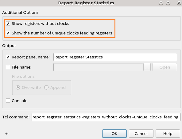
The Without a Clock column informs you of the number of registers where no defined clock feeds the registers in the hierarchy shown in the Register Count column. A value of 0 in this column suggests that your design has SDC-defined clocks feeding registers in the design. The Unique Clocks column indicates the number of unique SDC-defined clocks feeding registers in the hierarchy identified by the Register Count. To view these columns, enable Show registers without clocks and Show the number of unique clocks feeding registers additional options in the dialog that displays when you run the report, as shown in the following image:
Figure 72. Report Register Statistics Additional Options Dialog