Intel® Quartus® Prime Pro Edition User Guide: Timing Analyzer
A newer version of this document is available. Customers should click here to go to the newest version.
3.6.5.3. Creating Generated Clocks (create_generated_clock)
You apply generated clocks most commonly on the outputs of PLLs, on register clock dividers, clock muxes, and clocks forwarded to other devices from an FPGA output port, such as source synchronous and memory interfaces. In the .sdc file, enter generated clocks after the base clocks definitions. Generated clocks automatically account for all clock delays and clock latency to the generated clock target.
The -source option specifies the name of a node in the clock path that you use as reference for your generated clock. The source of the generated clock must be a node in your design netlist, and not the name of a clock you previously define. You can use any node name on the clock path between the input clock pin of the target of the generated clock and the target node of its reference clock as the source node.
Specify the input clock pin of the target node as the source of your new generated clock. By accepting a node as the generated clock's source clock, the generated clock constraint decouples from the source clock. If you change the source clock for the generated clock and the source node is the same, you do not have to edit the generated clock constraint.
If you have multiple base clocks feeding a node that is the source for a generated clock, you must define multiple generated clocks. You associate each generated clock with one base clock using the -master_clock option in each generated clock statement. In some cases, generated clocks generate with combinational logic.
Depending on how your clock-modifying logic synthesizes, the source or target node can change from one compilation to the next. If the name changes after you write the generated clock constraint, the Compiler ignores the generated clock because that target name no longer exists in the design. To avoid this problem, use a synthesis attribute or synthesis assignment to retain the final combinational node name of the clock-modifying logic. Then use the kept name in your generated clock constraint.
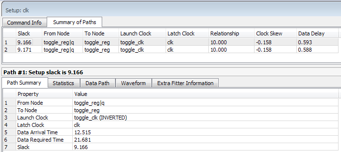
When you create a generated clock on a node that ultimately feeds the data input of a register, this creates a special case of “clock-as-data." The Timing Analyzer treats clock-as-data differently. For example, if you use clock-as-data with DDR, you must consider both the rise and the fall of this clock, and the Timing Analyzer reports both rise and fall. With clock-as-data, the Compiler treats the From Node as the target of the generated clock, and the Launch Clock as the generated clock.
In Example of clock-as-data, the first path is from toggle_clk (INVERTED) to clk, and the second path is from toggle_clk to clk. The slack in both cases is slightly different due to the difference in rise and fall times along the path. The Data Delay column reports the ~5 ps difference. Only the path with the lowest slack value requires consideration. The Timing Analyzer only reports the worst-case path between the two (rise and fall). In this example, if you do not define the generated clock on the register output, then timing analysis reports only one path with the lowest slack value.
You can use the derive_pll_clocks command to automatically generate clocks for all PLL clock outputs. The properties of the generated clocks on the PLL outputs match the properties you define for the PLL.