1. Nios II Custom Instruction Overview
2. Custom Instruction Hardware Interface
3. Custom Instruction Software Interface
4. Design Example: Cyclic Redundancy Check
5. Introduction to Nios® II Floating Point Custom Instructions
6. Nios II Floating Point Hardware 2 Component
7. Nios® II Floating Point Hardware (FPH1) Component
8. Document Revision History for Nios II Custom Instruction User Guide
4.1.1. Setting up the Environment for the CRC Example Design
4.1.2. Opening the Component Editor
4.1.3. Specifying the Custom Instruction Component Type
4.1.4. Displaying the Custom Instruction Block Symbol
4.1.5. Adding the CRC Custom Instruction HDL Files
4.1.6. Configuring the Custom Instruction Parameter Type
4.1.7. Setting Up the CRC Custom Instruction Interfaces
4.1.8. Configuring the Custom Instruction Signal Type
4.1.9. Saving and Adding the CRC Custom Instruction
4.1.10. Generating and Compiling the CRC Example System
6.1. Overview of the Floating Point Hardware 2 Component
6.2. Floating Point Hardware 2 IEEE 754 Compliance
6.3. IEEE 754 Exception Conditions with FPH2
6.4. Floating Point Hardware 2 Operations
6.5. Building the FPH2 Example Hardware
6.6. Building the FPH2 Example Software
6.7. FPH2 Implementation of GCC Options
6.8. Nios II FPH2 and the Newlib Library
6.9. C Macros for round(), fmins(), and fmaxs()
4.1.7. Setting Up the CRC Custom Instruction Interfaces
To set up the custom instruction interfaces, you use the Interfaces tab.
To set up the custom instruction interfaces, follow these steps:
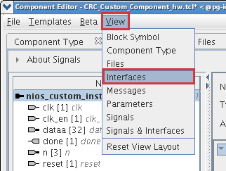
- In the View menu, click Interfaces to display the Interfaces tab.
Figure 17. Opening the Interfaces Tab

- If the Remove Interfaces With No Signals button is active, click it.
- Ensure that a single interface remains, with Name set to the name in the Signals tab. For the design example, maintain the interface name nios_custom_instruction_slave.
- Ensure the Type for this interface is Custom Instruction Slave.
- For Clock Cycles, type 0. This is the correct value for a variable multicycle type custom instruction, such as the CRC module in the design example. For other designs, use the correct number of clock cycles for your custom instruction logic.
- For Operands, type 1, because the CRC custom instruction has one operand. For other designs, type the number of operands used by your custom instruction.
Note: If you rename an interface by changing the value in the Name field, the Signals tab Interface column value changes automatically. The value shown in the block diagram updates when you change tabs and return to the Interfaces tab.Note: If the interface includes a done signal and a clk signal, the component editor infers that the interface is a variable multicycle type custom instruction interface, and sets the value of Clock Cycles to 0.