1.5.1. Simulation Diagrams
The simulation diagrams show the behavior of the signals in the design example.
Figure 11. Pattern Generator Starts Generating Fixed 1100 PatternThe pattern generator begins generating the fixed pattern to the Altera PHYLite output when the Altera PHYLite output generates the clock signal to the core through the core_clk_out port.
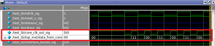
Figure 12. Interface Locked Signals from Altera PHYLite Instances The rdata_en, oe, and strobe_out_en signals of the Altera PHYLite input (ddr_in) and output (ddr_out) are always asserted after the interface_locked signal of the Altera PHYLite instances transitions from low to high. The interface_locked signal has to be high to indicate that all the necessary clocks in the Altera PHYLite instances function correctly.
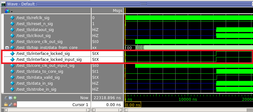
Figure 13. Generated Strobe Signal Edge-Aligned with Data Out SignalTo simulate the behavior of the Altera PHYLite output, the fixed serial 1100 pattern transmits through the Altera PHYLite output dataout pin after the interface_locked signal locks. The strobe_out_en signal remain asserted to generate the synchronous clock and strobe signals transmitted through the clkout pin with the Altera PHYLite output serial data.
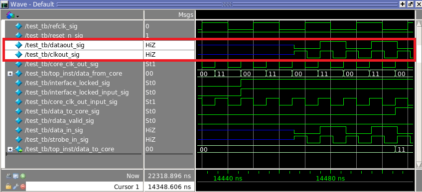
Figure 14. Data Out and Clock Out Signals LoopbackTo simulate the behavior of Altera PHYLite input instance, the dataout and clkout signals loop back to the data_in and strobe_in of the Altera PHYLite input interface.
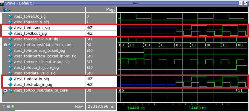
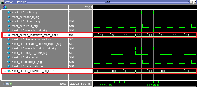
Figure 15. PHYLite Input Instance Transfers Valid Loopback Signals to the IP CoreThe loopback signals received by the PHYLite input instance transfer to the IP core when the rdata_valid signal is high.

Figure 16. Identical Received and Generated Data The data transfered to the IP core should look identical to the data generated by the pattern generator in the IP core.