Intel® Quartus® Prime Pro Edition User Guide: Design Constraints
A newer version of this document is available. Customers should click here to go to the newest version.
3.2.3.2. Assigning Dynamic Reconfiguration Group Placement
Once you load a design that includes dynamic reconfiguration groups, Tile Interface Planner displays the tile location of the dynamically reconfigurable IP instances and related building blocks. You can dynamically assign the tile location of IP instances within each dynamic reconfiguration group, and place other IP components in relation to the dynamic reconfiguration group. When placing other components, Tile Interface Planner takes all of the dynamic reconfiguration group placements into account.
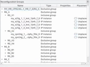
The Reconfiguration Groups view shows the members and placement of the dynamic reconfiguration groups that you create. Use the Reconfiguration Groups view to select the dynamic reconfiguration group that you want to assign. You can only modify the DR groupings in Tile Assignment Editor, not in Tile Interface Planner.
- Define one or more dynamic reconfiguration groups, as Defining a Dynamic Reconfiguration Group describes.
- To run Logic Generation, click double-click Logic Generation on the Compilation Dashboard.
- To start Tile Interface Planner, click the Tile Interface Planner icon on Compilation Dashboard, as Step 2: Initialize Tile Interface Planner describes.
- In Tile Interface Planner, click the Plan tab. Tile Interface Planner displays the dynamic reconfiguration IP profiles in the Design Element hierarchy.
- Select an instance in the Reconfiguration Groups tree view, the selection synchronizes with the selection in the Design Elements lists.
Figure 45. Reconfiguration Groups and Design Elements Selection Synchronization
- Click the
 button next to the Design Element to display a list of Legal Locations for the selected DR group.
 - Double-click any location in Legal Locations to place the element in a legal location. Tile Interface Planner places the IP in the legal location on the device tile.
- Place other IP components in relation to that location, as Placing IP Components describes. Tile Interface Planner takes the dynamic reconfiguration group placement into account when you place other IP components.
Figure 46. Placing Other IP Components