Intel® Quartus® Prime Pro Edition User Guide: Design Constraints
A newer version of this document is available. Customers should click here to go to the newest version.
4.5.1.1. Board Trace Models
The Intel® Quartus® Prime software provides board trace model templates for various I/O standards.
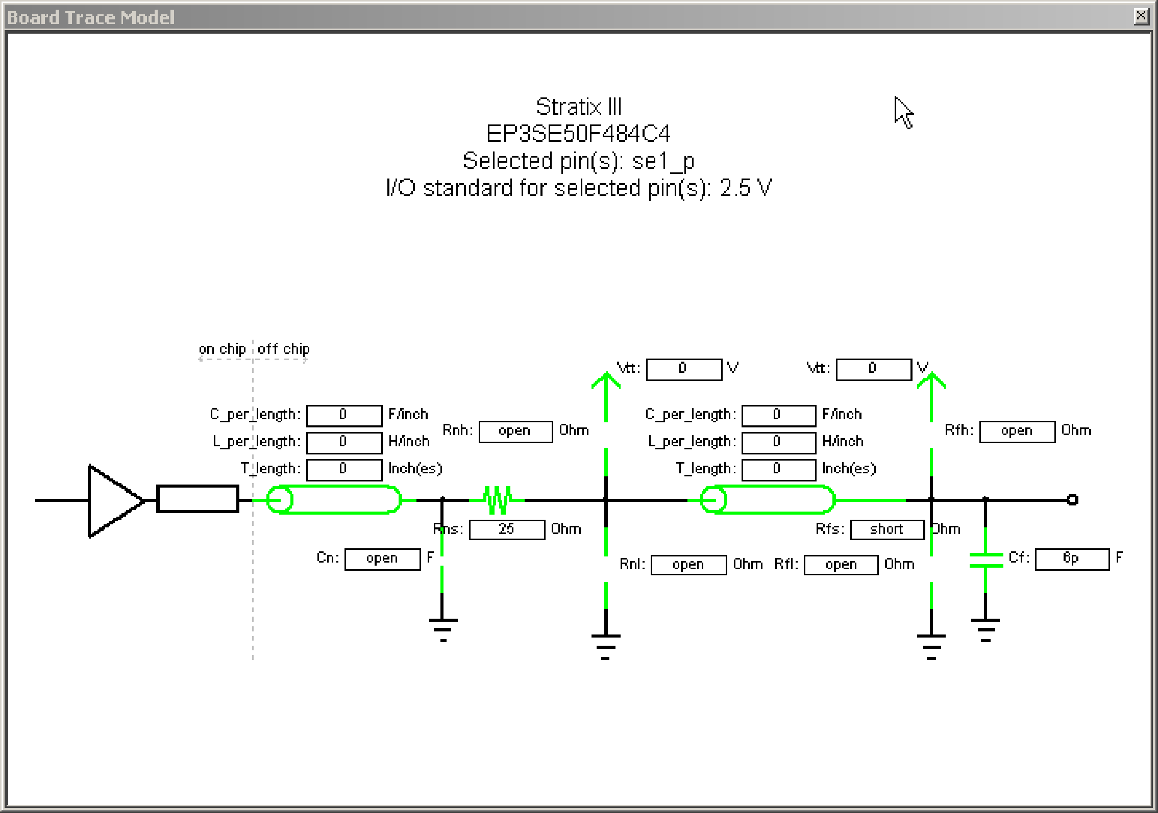
The following figure shows the template for a 2.5 V I/O standard. This model consists of near-end and far-end board component parameters.
Near-end board trace modeling includes the elements which are close to the device. Far-end modeling includes the elements which are at the receiver end of the link, closer to the receiving device. Board trace model topology is conceptual and does not necessarily match the actual board trace for every component. For example, near-end model parameters can represent device-end discrete termination and breakout traces. Far-end modeling can represent the bulk of the board trace to discrete external memory components, and the far end termination network. You can analyze the same circuit with near-end modeling of the entire board, including memory component termination, and far-end modeling of the actual memory component.
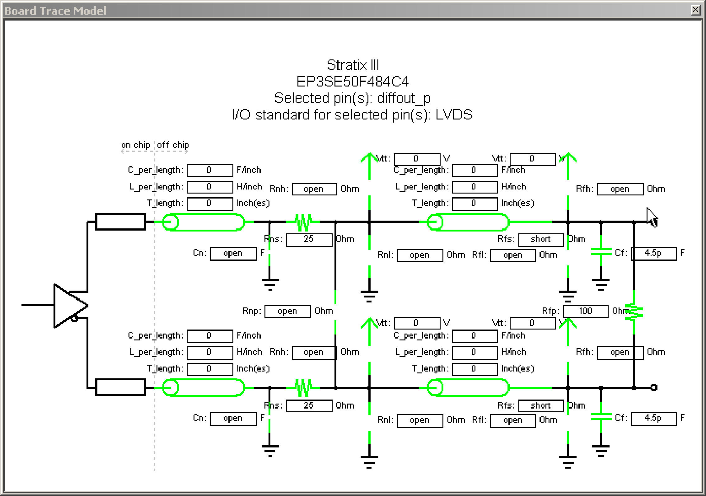
The following figure shows the template for the LVDS I/O standard. The far-end capacitance (Cf) represents the external-device or multiple-device capacitive load. If you have multiple devices on the far-end, you must find the equivalent capacitance at the far-end, taking into account all receiver capacitances. The far-end capacitance can be the sum of all the receiver capacitances.
The Intel® Quartus® Prime software models of transmission lines do not consider transmission-line resistance (lossless models). You only need to specify distributed inductance (L) and capacitance (C) values on a per-inch basis, which you can obtain from the PCB vendor or manufacturer, the CAD Design tool, or a signal integrity tool, such as the Mentor Graphics* HyperLynx* software.