1. Introduction to Agilex™ 3 FPGA Thermal Design Guidelines
2. Agilex™ 3 FPGA Mechanical Construction
3. Agilex™ 3 FPGA Compact Thermal Model (CTM) Construction
4. Power and Thermal Calculator (PTC)
5. Thermal Design Process
6. General FPGA Thermal Design Considerations
7. Design Examples
8. Heat Sinks
9. Document Revision History for the Thermal Design User Guide: Agilex™ 3 FPGAs and SoCs
A. Agilex™ 3 FPGA Product Keys and Package Drawings
7.3. Example 3: Find the Ambient Temperature for a Specified Cooling Solution
In this example you have a thermal solution already assigned or available, and the TJ-MAX of the device is set. You must determine the maximum ambient temperature under which this thermal solution works. The example assumes the heat sink has an effective ΨCA of 20°C/W.
The module’s thermal solution includes a 50mm x 50mm x 25mm heat sink, no air flow, and the device is on a 10-layer board.
From the table in the Variables Affecting the Heat Flow Path topic, we know that the percentage heat transfer to the heat sink is 55%.
To input the cooling solution ΨCA value into the PTC Thermal tab, you perform the following calculation:

In the PTC Thermal tab, choose the calculation mode as Find ambient temperature for specified cooling solution.
Input the ΨCA of 11°C/W and the TJ-MAX of 100°C.
Figure 14. Example 3, PTC Main tab
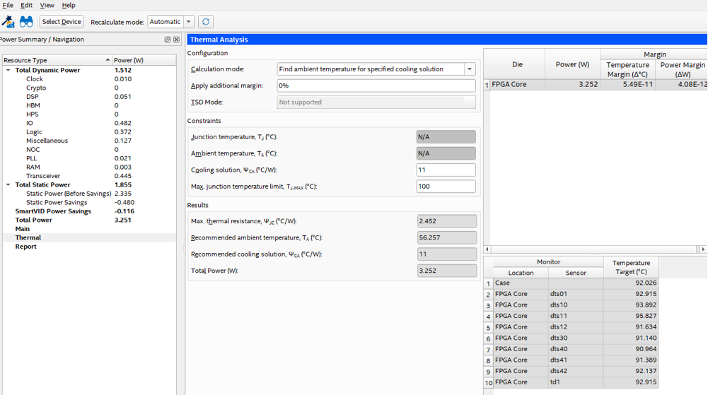
The PTC Thermal tab indicates that the cooling solution is adequate for an ambient temperature of up to 56°C.