1. Introduction to Agilex™ 3 FPGA Thermal Design Guidelines
2. Agilex™ 3 FPGA Mechanical Construction
3. Agilex™ 3 FPGA Compact Thermal Model (CTM) Construction
4. Power and Thermal Calculator (PTC)
5. Thermal Design Process
6. General FPGA Thermal Design Considerations
7. Design Examples
8. Heat Sinks
9. Document Revision History for the Thermal Design User Guide: Agilex™ 3 FPGAs and SoCs
A. Agilex™ 3 FPGA Product Keys and Package Drawings
2. Agilex™ 3 FPGA Mechanical Construction
Agilex™ 3 FPGAs are lidless square flip-chip BGA devices and are offered in various sizes. The leadless solder balls have variable pitch, ranging from 0.5mm to 0.94mm. The following example figure shows the mechanical drawing for an Agilex™ 3 FPGA, part number A3C-135-B18A.
Figure 2. Agilex™ 3 FPGA, A3C-135-B18A
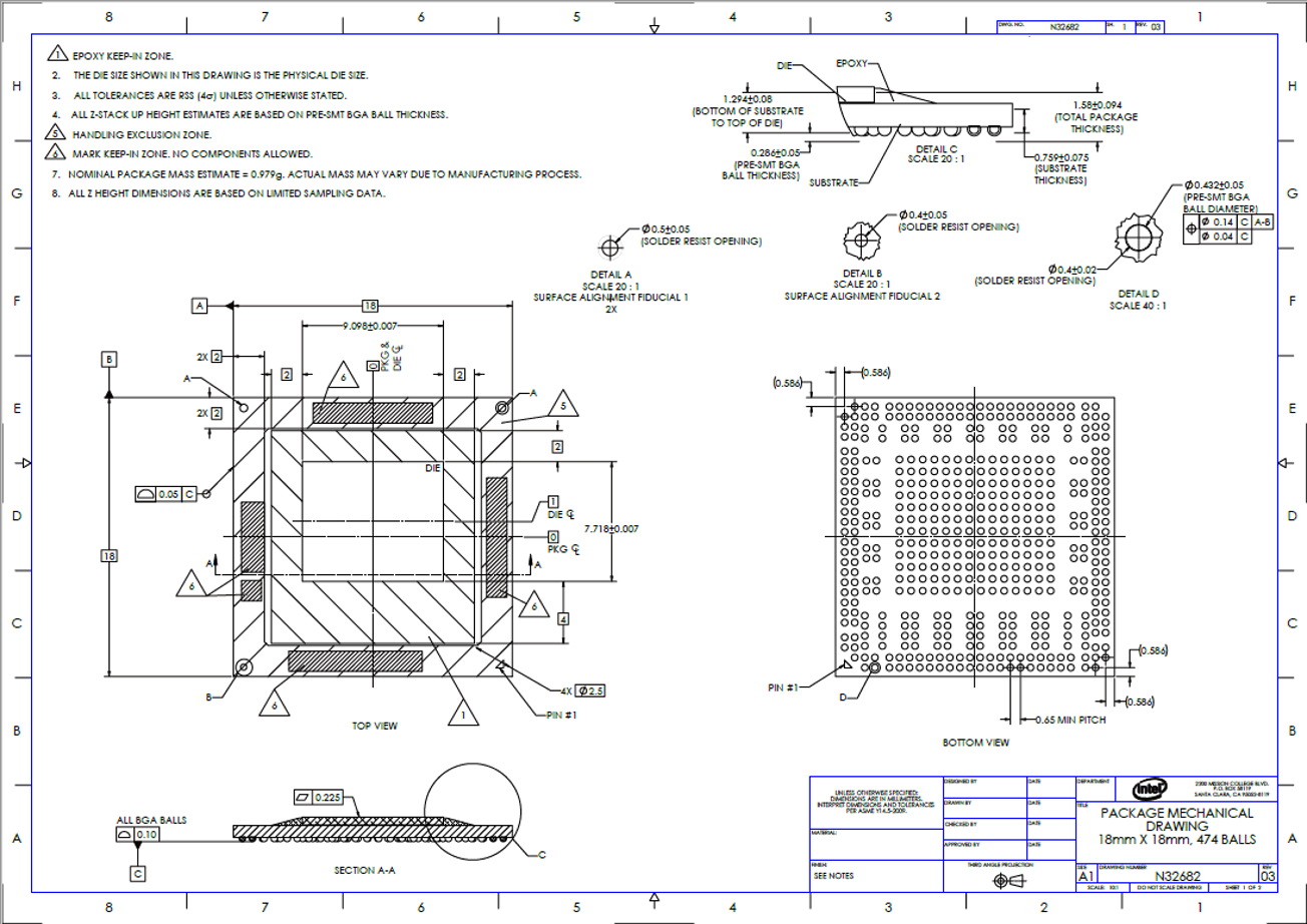
Be aware that there are capacitors on top of the substrate and therefore there are keep-out zones that you should observe to avoid any physical interference for general system packaging and cooling solutions. (Refer to Agilex™ 3 FPGA Product Keys and Package Drawings for Agilex™ 3 product keys and mapping to available package drawings.