8.2.1.2. Understanding Resistance and Pressure Map Curves
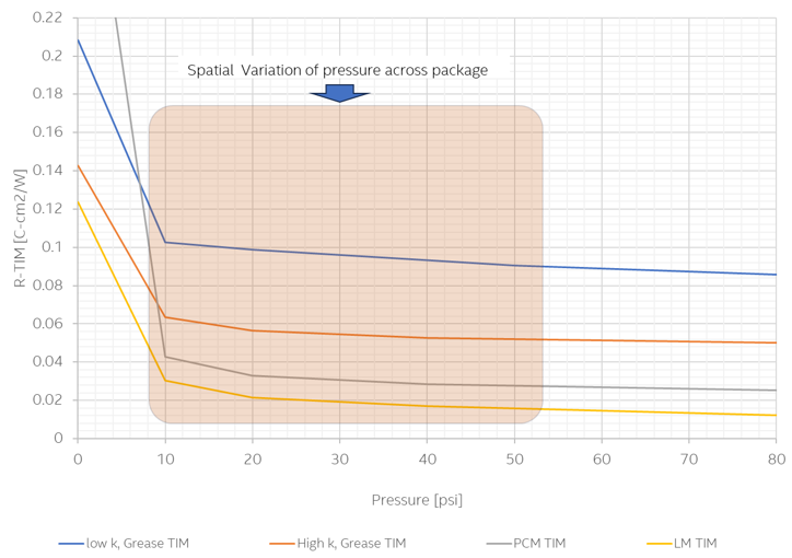
Two graphs have been plotted separately for Gap Pads and other TIM materials due to the significantly higher resistances of Gap Pads, which are one order of magnitude higher compared to other TIMs. As illustrated below, resistances are higher initially or in low-pressure regions. However, as pressure increases, resistance decreases, indicating the establishment of effective contact between two solid surfaces, such as the heat source and heat sink materials. Beyond a certain pressure threshold, the variation becomes asymptotic, with limited gains in resistance reduction.
The following figure shows the measured curves for initial Gap Pad thicknesses in the range of 0.8 to 1.2 mm reveal that performance varies based on material composition and manufacturer. These are provided as a best guide for typical lidless low-power FPGA applications. However, the appropriate Gap Pad thickness can be selected based on the gap between the package and heatsink requirements.
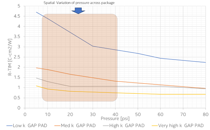
The appropriate Gap Pad thickness can be selected based on the gap between the package and heatsink requirements.
In the following figure, the measured curves reveal that metallic TIMs exhibit the lowest thermal resistance, followed by phase-change materials and grease TIMs. These are provided as a best guide for both lidded and lidless medium to high-power FPGA applications
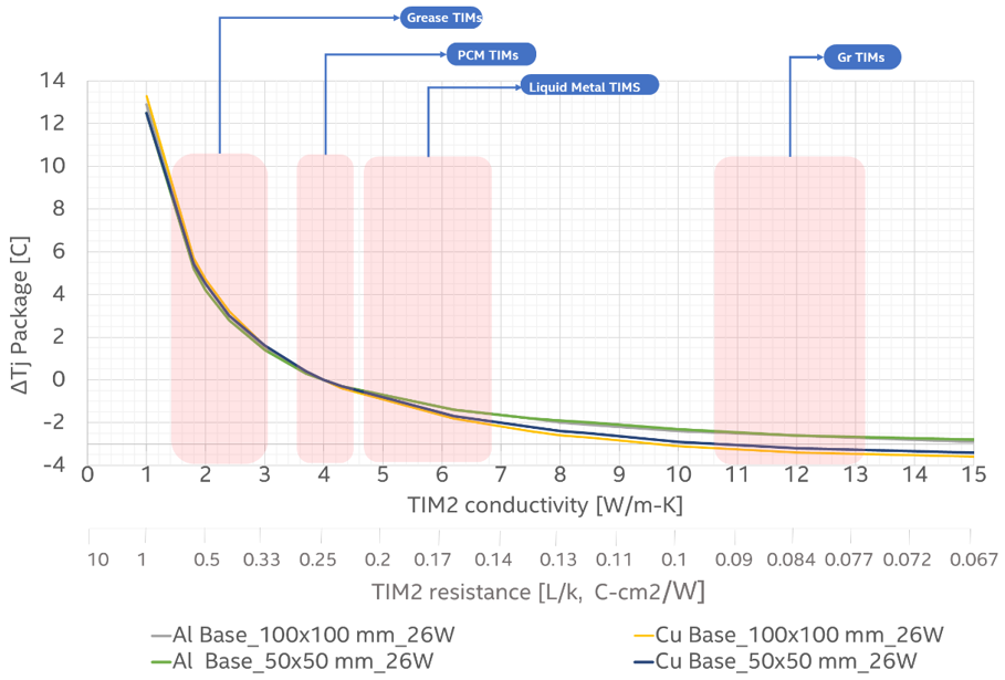
To estimate the impact of varying TIM2 thermal conductivity on the package TJ, a mid-power device was selected with a standard heat sink and a TIM2 of certain thickness and thermal conductivity of 4 W/mK as the baseline. Only the TIM2 conductivity was varied.
The following figure shows the change in TJ for mid-range power devices, with change in TIM2 conductivity, assuming the baseline TIM2 conductivity is 4 W/mK. It can be seen that for thermal conductivities between 2 to 6 W/mK, the impact of TIM2 materials on lidless packages thermal performance is relatively significant, of the order of 5oC. Beyond 6 W/mK, even when employing heat sink solutions with different base materials, high conductivity TIMs do not significantly enhance performance, where the package temperature impact is less than 2°C.
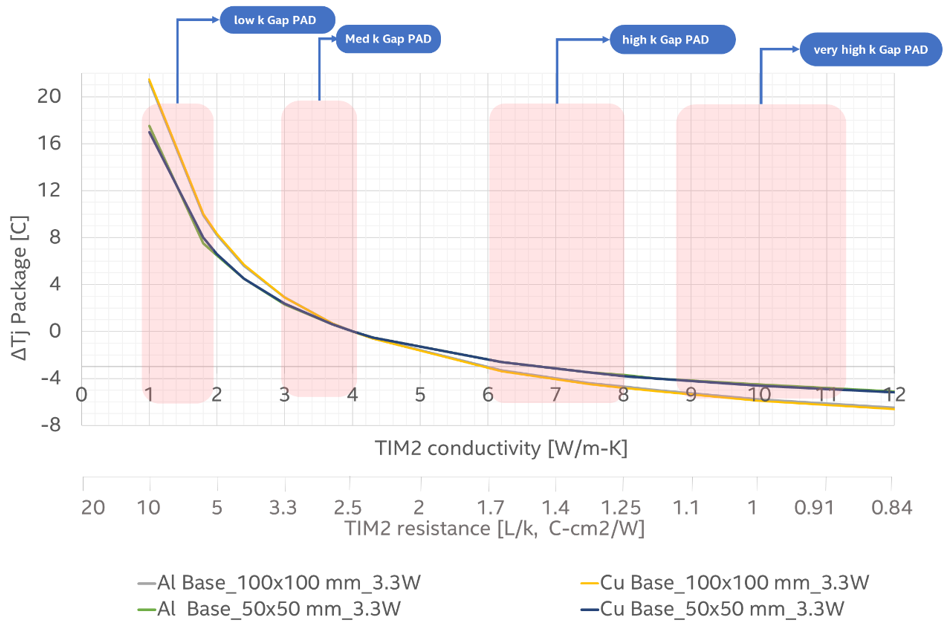
A similar comparison was done for low-power Agilex™ 3 devices with a TIM2 thermal conductivity of 4W/mK as the baseline. As illustrated in the figure below, for low-power applications using thicker Gap Pads, TIM2 thermal conductivity significantly enhances thermal performance, up to a TIM2 k value of about 8W/m-K. Beyond this threshold, high-performance TIM2 materials have only a marginal impact on thermal performance. For these applications typically Gap Pads are primary choice due to cost and higher gap between package and heatsink. The thickness depends on the gap between package and the heat sink, and the usual range is of the order of 0.8 to 1.2 mm