1. Introduction to Agilex™ 3 FPGA Thermal Design Guidelines
2. Agilex™ 3 FPGA Mechanical Construction
3. Agilex™ 3 FPGA Compact Thermal Model (CTM) Construction
4. Power and Thermal Calculator (PTC)
5. Thermal Design Process
6. General FPGA Thermal Design Considerations
7. Design Examples
8. Heat Sinks
9. Document Revision History for the Thermal Design User Guide: Agilex™ 3 FPGAs and SoCs
A. Agilex™ 3 FPGA Product Keys and Package Drawings
3. Agilex™ 3 FPGA Compact Thermal Model (CTM) Construction
Compact thermal models (CTMs) are CAD models that are used in CFD tools.
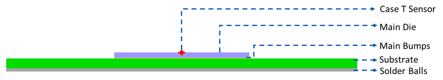
CTMs do not include the full detail of the mechanical design — features such as solder bumps, vias, or substrates, are simplified. CTMs are tuned to provide accurate results for the thermal analysis methodology described in this document.
The CTM for the FPGA in the previous topic is designated as ctm-A3C-135-B18A. The following figure illustrates the general construction of Agilex™ 3 FPGA CTM models. Your only input to the CTM is the power of the die and the only valid output from the CFD results is the temperature of the die at the top center and the amount of heat dissipated from the top and bottom of the FPGA.
Figure 4. CTM Construction