7.1. Example 1: Find Cooling Solution for Maximum Junction Temperature Limit
In this mode, you enter the ambient temperature near the device and the maximum TJ value on the Thermal tab of the Power and thermal Calculator (PTC).
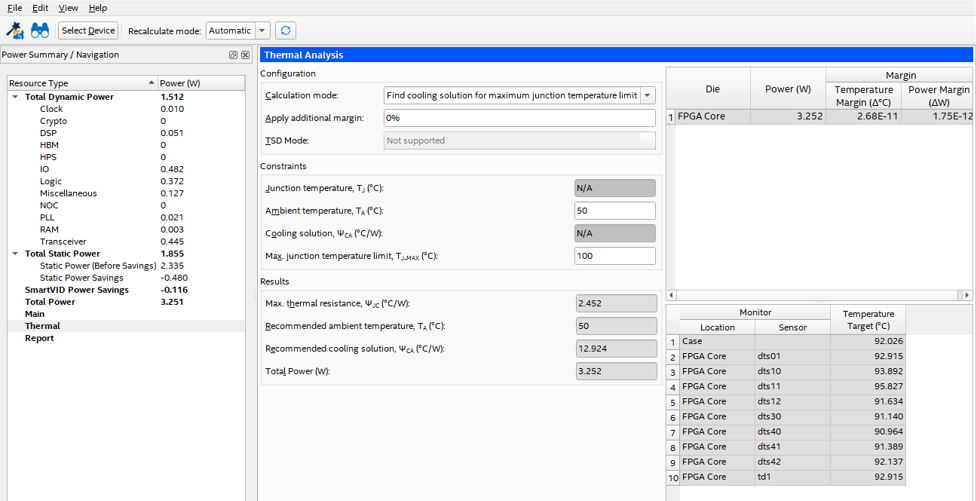
This example assumes the following values:
- Ambient T = 50°C
- TJ-MAX for the device = 100°C
This results in a device power of 3.25W and a required ΨCA of 12.9°C/W.
The recommended ΨCA output from the PTC is calculated assuming that all the heat generated in the FPGA goes out through the top and no heat goes out to the PCB; this results in a ΨCA value that corresponds to a large heat sink or a large airflow.
In the module, a significant amount of the heat goes through to the PCB. Referring to the table in the Variables Affecting the Heat Flow Path topic, for the following conditions - heat sink 50mm x 50mm x 25mm, no air flow and on a 10-layer board, the percentage heat through to the heat sink is only 55%.
This indicates that the heat sink ΨCA value from the PTC must be scaled for this heat. It thus becomes:

The cooling solution requirement is thus 23.4°C/W