GTS AXI Streaming IP for PCI Express* Design Example User Guide
ID
817713
Date
10/23/2025
Public
2.1. Directory Structure
2.2. Generating the Design Example
2.3. Simulating the Design Example
2.4. Design Example Simulation Testbench
2.5. Compiling the Design Example
2.6. Hardware and Software Requirements
2.7. Program the FPGA
2.8. Installing the Linux Kernel Driver
2.9. Running the Design Example
A.1.1. ebfm_barwr Procedure
A.1.2. ebfm_barwr_imm Procedure
A.1.3. ebfm_barrd_wait Procedure
A.1.4. ebfm_barrd_nowt Procedure
A.1.5. ebfm_cfgwr_imm_wait Procedure
A.1.6. ebfm_cfgwr_imm_nowt Procedure
A.1.7. ebfm_cfgrd_wait Procedure
A.1.8. ebfm_cfgrd_nowt Procedure
A.1.9. BFM Configuration Procedures
A.1.10. BFM Shared Memory Access Procedures
A.1.11. BFM Log and Message Procedures
A.1.12. Verilog HDL Formatting Functions
2.9.2. Running the Single Root I/O Virtualization (SR-IOV) Design Example
Before you can test the design example in hardware, you must enable SR-IOV and ARI (Alternative Routing ID Interpretation) in the BIOS, configure the FPGA, and then restart your computer to allow the enumeration to take place for the PCIe device. After that, install the Linux kernel driver as described in Installing the Linux Kernel Driver.
Here are the steps to test the SR-IOV design example on hardware:
- In the host system, navigate to the ./software/user/example directory of the software driver.
- Compile the design example software application by running the make command:
$ make
- Run the test by running the following command:
$ sudo ./intel_fpga_pcie_link_test
- Select Option 1: Manually Select a Device to specify the Bus-Device-Function (BDF) of the Physical Function (PF) to which the Virtual Functions (VFs) are assigned.
- Enter BAR “0” to proceed to the test menu.
- Enter option 7 to enable SR-IOV for the current device.
- Enter the number of virtual functions to be enabled for the current device.
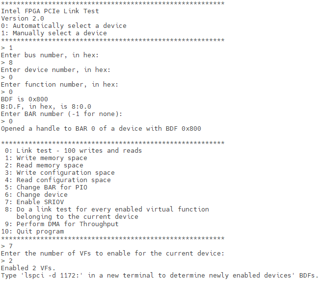 Note: To disable VF for the current device, repeat Step 6: Select option 7 to enable SR-IOV, enter 0 for the number of VFs to be enabled.Note: Type 'lspci -d 1172:' in a new terminal to determine the BDFs of the newly enabled VFs.
 - In a new terminal, run the
$ sudo lspci –d 1172: | grep -c “Altera”
command to verify the enumeration of PFs and VFs. The expected result is the sum of the number of physical functions and the number of virtual functions. In this test case, the expected result is 4 (2 PF + 2 VF).

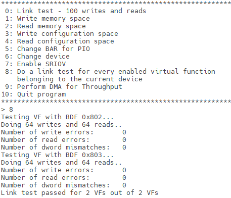
- Enter Option 8 to initiate a link test for each enabled VF associated with the specified PF. The link test application performs 64 memory write operations, each writing a single DW of data, followed by corresponding read operations to verify data integrity. Upon completion, the application reports the number of VFs that failed the link test.
Note: This test is only supported when targeting the BDF of the designated PF.