Device Migration Guidelines: Agilex™ 5 FPGAs and SoCs E-Series
ID
813955
Date
6/06/2025
Public
4.1. Migration via Migration GUI for Agilex™ 5 E-Series Devices
The example design used in this migration is a basic design to address the pin assignment and the I/O standard issues.
- To start the device migration, right-click on the device tab in the Project Navigator window. This will navigate you to a pop-up window as shown in the following figure.
Figure 14. Device Page
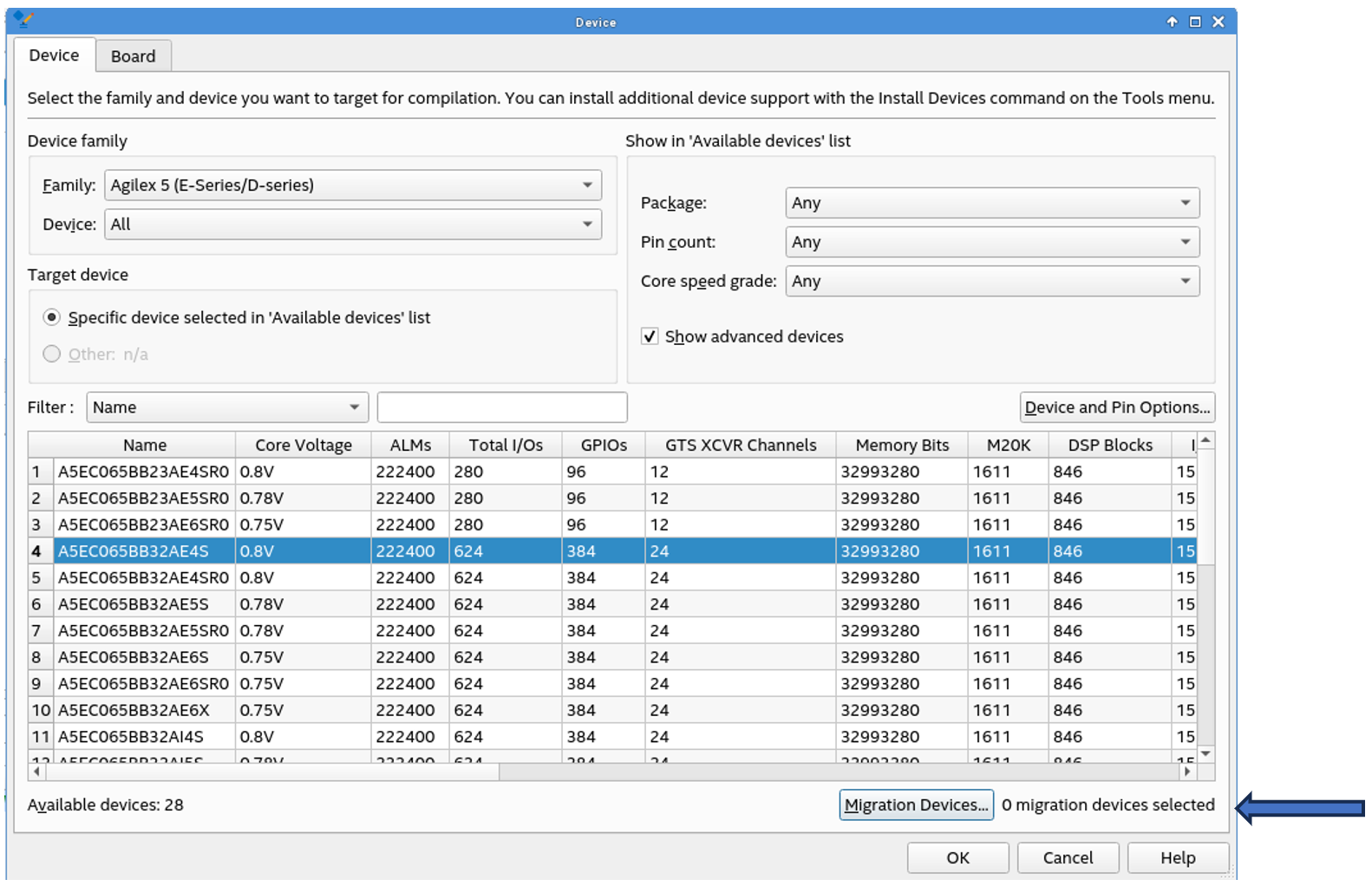
- Instead of changing the device directly (which will allow the Quartus® Prime software to migrate to a new device by removing all the location assignments), select the Migration Devices tab located at the bottom right of the window as shown in Device Page. When you select the Migration Devices tab, a pop-up window will appear as shown in the following example figure.
Figure 15. Migration Devices
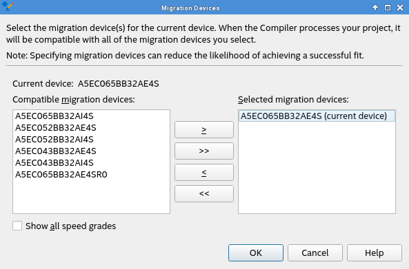
- In the Migration Devices dialog box, click on the arrow buttons to move the migration devices between the Compatible migration devices list and the Selected migration devices list.
Compatible devices are listed in the Compatible migration devices list. If you want the Quartus® Prime software to display all compatible migration devices in the Compatible migration devices list regardless of a migration device's speed grade, turn on the Show all speed grades option. If you want the Quartus® Prime software to display only the compatible migration devices that have the same speed grade as the target device in the Compatible migration devices list, uncheck the Show all speed grades option.
- After choosing the device for migration, click OK. If you do not specify at least one migration device in the Migration Devices dialog box, the field next to Migration Devices tab in the Device window displays 0 migration devices selected.
- After specifying the device to use as a migration device, compile the design. However, the device migration may cause additional constraints. Compilation may fail due to the additional constraints, and the errors prompt you to check the pin assignments in the Pin Planner as shown in the following figure.
Figure 16. Pin Planner
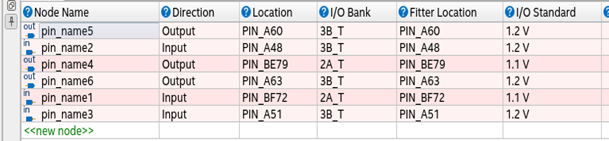
- For the non-migratable I/O pins, leave them as NC. You can set the unused I/O pins as input tri-state in the Intel Quartus Prime software.
Go to Device from the Project Navigator window and click on Devices and Pin Options as shown in the following figure. In the Devices and Pin Options window, under the Reserve all unused pins drop-down list, select As input tri-stated.
Figure 17. Device Page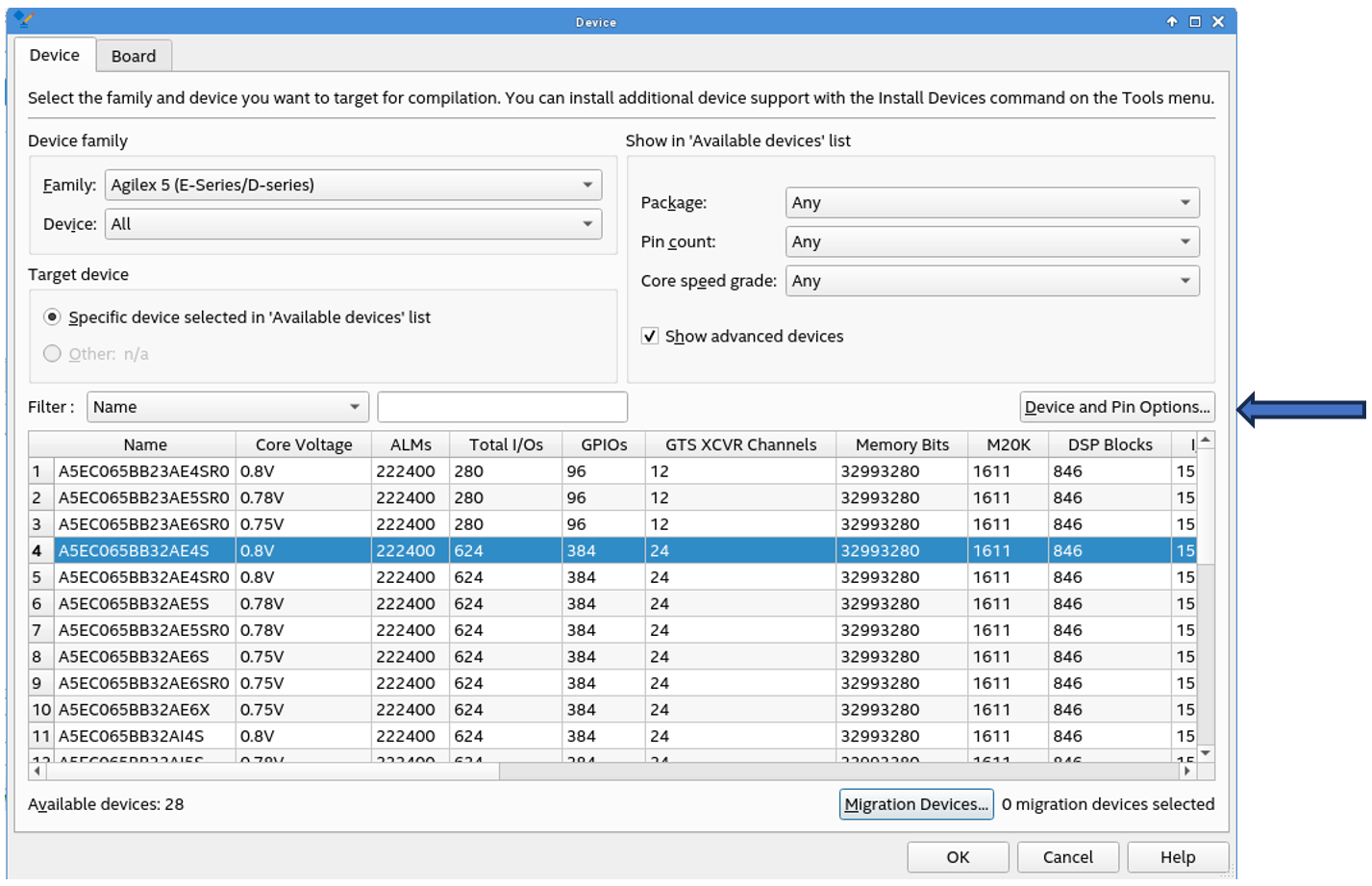 Figure 18. Devices and Pin Options
- Remove the location assignment of the non-migratable pins as shown in the following figure and compile the design.
Figure 19. Location Assignment
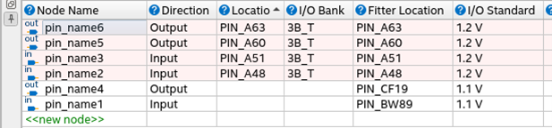 Figure 20. Design Compilation
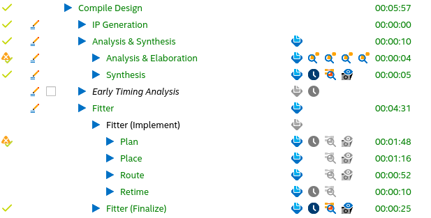
- If you have the flexibility of changing the non-migratable pins and their I/O standards, you can go the Pin Migration View window and check the pins compatibility and assign the pins accordingly.
- The Pin Migration View window provides information about the suitability of the pins for device migration, as shown in the following figure. You can open this window in the Pin Planner by clicking View > Pin Migration View. Select a pin in this view to display the following pin migration information:
- Pin number
- Migration result
- Migration devices
You can access the following commands by right-clicking on the Pin Migration View window in the Pin Planner:
- Device
- Pin Finder
- Show Only Highlighted Pins
- Show Migration Differences
- Export
- Show Columns
Figure 21. Pin Migration View
You can look in the Pin Finder to find the pins according to the requirement as shown in the following figure.
Figure 22. Pin Finder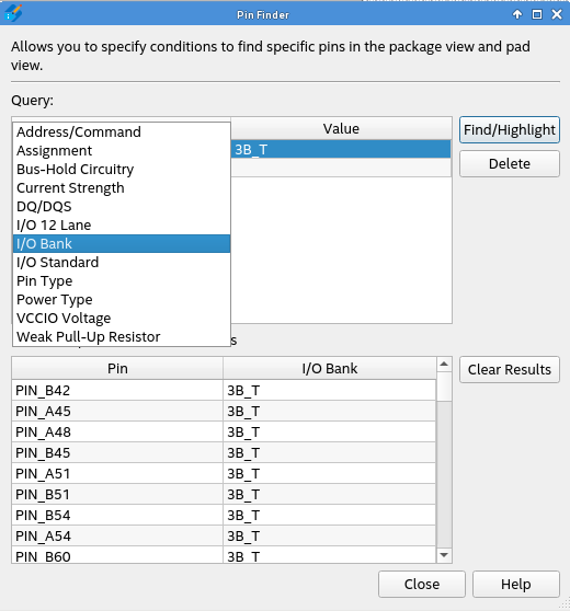
- Change the pin assignment in the Pin Planner as shown in the following figure and compile the design to achieve a successful compilation.
Figure 23. Pin Assignments
