3. Parameters
| Parameter | Supported Values | Default Setting | Description |
|---|---|---|---|
| General Options | |||
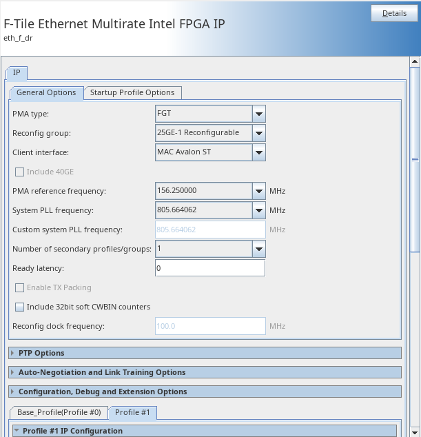
| PMA type | FGT FHT |
FGT | Selects the targeted transceiver type in the F-tile.
|
| Reconfig group | FGT: 25GE-1 Reconfigurable 50GE-1 Reconfigurable 100GE-4 Reconfigurable 100GE-2 Reconfigurable 200GE-4 Reconfigurable 400GE-8 Reconfigurable FHT: 100GE-1 Reconfigurable 200GE-2 Reconfigurable 400GE-4 Reconfigurable |
25GE-1 Reconfigurable | Selects the reconfiguration group. The reconfiguration group indicates the base profile along with the maximum number of transceivers used within the group. |
| Client interface | MAC Avalon® Streaming Interface MAC segmented MII PCS only PCS66 OTN PCS66 FlexE |
MAC segmented | Selects data interface exposed to a client. |
| Include 40GE | On Off |
Off | When disabled, removes the 40GE bridge logic from the F-Tile Ethernet Multirate IP core. |
| PMA reference frequency | 156.250000 312.500000 322.265625 |
156.250000 | Selects the reference clock frequency used by the transceiver. When System PLL frequency is not set to Custom, the transceiver and the system clock must connect to the same reference clock or to references that are PPM locked. |
| System PLL frequency | 805.664062 830.078125 Custom |
805.664062 | Selects the System PLL frequency. Each reconfiguration group defines the minimum system PLL frequency. For reconfiguration group supporting PAM4 profile, the minimum system PLL frequency is 830 MHz. Use Custom when you require other frequencies or if system PLL reference clock source and PMA reference clock source are different. You must define Custom System PLL Frequency parameter value. |
| Custom system PLL frequency | 805.6640625M - 1 GHz | N/A | If you choose the Custom option in the System PLL Frequency parameter, the IP core clock o_clk_pll is equivalent to half of the specified rate. The frequency must be greater than the minimum system PLL frequency defined for each reconfiguration group. For information about clock frequency ranges, refer to Clock Signals. |
| Number of secondary profiles/groups | 1-32 | 1 | Selects the number for the secondary profiles or profile groups. Each secondary profile enables a new tab in the IP GUI. For example, setting Number of secondary profiles/groups to 4 generates four secondary profile tabs. |
| Enable TX Packing | On Off |
Off | This parameter is available when client interface is set to MAC segmented mode with no PTP for the following reconfiguration groups:
The implementation details for the packing logic can be found in the F-tile Ethernet Intel FPGA Hard IP User Guide. |
| Ready Latency | 0-3 | 0 | Selects the ready latency value on the TX client interface Ready Latency is an Avalon ST interface property that defines the number of clock cycles of the delay from when the IP core asserts the o_tx_ready signal to the clock cycle in which the IP core can accept the data on the TX client interface. Refer to Avalon Interface Specifications. Selecting a longer latency (higher number) eases timing closure at the expense of increased latency for the TX datapath in MAC+PCS variations. This parameter is only available if Client Interface is set to MAC Avalon ST. |
| Enable asynchronous adapter clocks | On Off |
Off | When turned on, you can drive the i_clk_rx and i_clk_tx clock signals different from o_clk_pll clock signal. This parameter is only available if client interface is set to MAC Avalon ST. |
| Include 32-bit soft CWBIN counters | On Off |
Off | This parameter is available when FEC mode is enabled in the IP parameter editor. This soft logic converts the 8-bit CWBin0-3 registers in Hard IP (FEC block of F-tile) to the 32-bit registers in Soft logic. |
| Reconfig Clock Frequency | 100 to 250 MHz | 100 MHz | The Avalon® memory-mapped interface uses this clock to access control status registers (CSRs). The clock supports the frequency range of 100 to 250 MHz. |
| Startup Profile Options | |||
| Startup profile | 1x25GE-1/10GE-1 2x25GE-1/10GE-1 4x25GE-1/10GE-1 1x40GE-4 1x50GE-1 1x50GE-2 2x50GE-1 2x50GE-2 1x100GE-1 1x100GE-2 1x100GE-4 1x200GE-2 4x100GE-2 2x200GE-4 1x400GE-4 1x400GE-8 |
Varies based on the selected base profile | Selects the startup profile within each reconfiguration group. The available options depends on the base profile. When you select a non-base profile as the startup profile, ensure the secondary profile is also generated and set as the startup profile in the QSF settings.
The following options are available for FGT transceivers:
|
| Startup profile - Port <0-N> | None Profile-0 (Base Profile) Profile 1-N (N is the number of secondary profiles or profile groups) |
None | Selects the startup profile number associated with each port.
|
| Parameter | Supported Values | Default Setting | Description |
|---|---|---|---|
| PTP Options 6 | |||
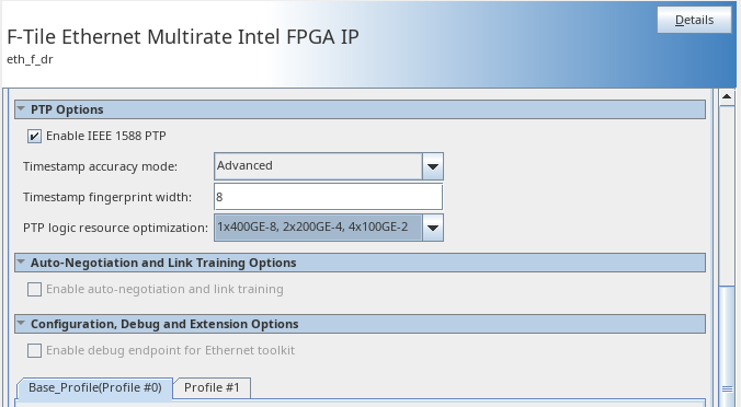
| Enable IEEE 1588 PTP | On Off |
Off | Enable this option to add IEEE 1588 PTP Timestamp offload functions to the IP core. The IP core can generate TX timestamps and RX timestamps. |
| Timestamp accuracy mode | Basic Advanced |
Advanced | Select PTP TX and RX timestamps accuracy mode.
In Basic mode, supports the following timestamps accuracy:
In Advanced mode, supports the following timestamps accuracy:
Note: The timestamp accuracy values in Advanced modes is not available for some secondary profiles.
Important: The timestamp accuracy values in Basic and Advanced modes reflect simulation results only. Hardware accuracy values may differ and will be available in a future release.
|
| Timestamp fingerprint width | 8 - 32 | 8 | Specify the width of the timestamp fingerprint in bits on the TX path. The default value is 8 bits. |
| PTP Logic Resource Optimization | The following options are available for FGT transceivers:
25GE-1 Reconfigurable
50GE-1 Reconfigurable
100GE-4 Reconfigurable
100GE-2 Reconfigurable:
200GE-4 Reconfigurable:
400GE-8 Reconfigurable
|
Varies based on the selected reconfiguration group. The default option enables all ports and ethernet rates. | Determines the number of active ports and Ethernet rates available when PTP is enabled. The Intel® Quartus® Prime software does not synthesize the PTP logics of unused ports or Ethernet rates of a reconfiguration group This parameter is only available if PMA type is set to FGT. |
| Parameter | Supported Values | Default Setting | Description |
|---|---|---|---|
| Profile #0 IP Configuration | |||
| Ethernet mode | 25GE-1 50GE-1 100GE-1 100GE-2 100GE-4 200GE-2 200GE-4 400GE-4 400GE-8 |
25GE-1 | Displays the default base profile per the selected reconfiguration group. |
| FEC mode | None IEEE 802.3 BASE-R Firecode (CL74)7 IEEE 802.3 RS(528,514) (CL91) IEEE 802.3 RS(544,514) (CL134) Ethernet Technology Consortium RS(272, 258) |
None | Selects the FEC mode for base profile.
The IP core supports the following FEC types
Note: Not all FEC modes are available for all base profiles.
|
| Associated Port Number | 0: Port 0 1: Port 1 2: Port 2 3: Port 3 4: All |
Port 0 |
Selects the port number associated with the current secondary profile.
Note: The active ports depends on the selected Ethernet mode. Not all active ports are available.
This parameter is specific to the secondary profiles. |
| MAC settings same as Profile<n>, where <n> is the profile number | On Off |
Off | When enabled, the port 0 contains the MAC parameter settings. When disabled, you select a unique MAC parameters for the currently selected secondary profile. This parameter is specific to the secondary profiles. |
| Profile #0 MAC Options | |||
| P0 Basic |
|||
| TX maximum frame size |
65 – 65535 | 1518 |
Maximum packet size (in bytes) the IP core can transmit on the Ethernet link without reporting an oversized packet in the TX statistics counters. In PCS Only, OTN, and FlexE variations, this parameter has no effect and remains at the default value of 1518. |
| RX maximum frame size |
65 – 65535 | 1518 |
Maximum packet size (in bytes) the IP core can receive on the Ethernet link without reporting an oversized packet in the RX statistics counters. If you turn on Enforce Maximum Frame Size parameter, the IP core truncates incoming Ethernet packets that exceed this size. In PCS Only, OTN, and FlexE variations, this parameter has no effect and remains at the default value of 1518. |
| Enforce maximum frame size | On Off |
Off | Specifies whether the IP core is able to receive an oversized packet or truncates these packets. In a truncated packet, error signal indicates oversize and FCS error. |
| Link fault generation option | Off Unidirectional Bidirectional |
Bidirectional | Specifies the IP core response to link fault events. Bidirectional link fault handling complies with the Ethernet specification, specifically IEEE 802.3 Figure 81-11. Unidirectional link fault handling implements IEEE 802.3 Clause 66: in response to local faults, the IP core transmits Remote Fault ordered sets in interpacket gaps but does not respond to incoming Remote Fault ordered sets. The OFF option is provided for backward compatibility. |
| Bytes to remove from RX frames | None Remove CRC bytes Remove CRC and PAD bytes |
Remove CRC bytes | Selects whether the RX MAC should remove CRC bytes, or remove CRC and PAD bytes, or do not remove anything from incoming RX frames before passing them to the RX MAC Client. If the PAD bytes and CRC are not needed downstream, this option can reduce the need for downstream packet processing logic |
| Forward RX pause requests | On Off |
Off | Selects whether the RX MAC forwards incoming PAUSE and PFC frames on the RX client interface, or drops them after internal processing.
Note: If flow control is turned off, the IP core forwards all incoming PAUSE and PFC frames directly to the RX client interface and performs no internal processing. In that case this parameter has no effect.
|
| Use source address insertion | On Off |
Off | Selects whether the IP core inserts source address in the outgoing packets. |
| TX VLAN detection | On Off |
Off | When selected VLAN and Stacked VLAN Ethernet types cause TX MAC to count frame as VLAN/SVLAN” Recognized Ethernet types: ‘h8100, 'h88A8, 'h88F5, 'h9100, 'h9200 |
| RX VLAN detection | On Off |
Off | Specifies whether the IP core RX statistics block treats RX VLAN and Stacked VLAN Ethernet frames as regular control frames, or performs Length/Type field decoding, includes these frame in VLAN statistics, and counts the payload bytes instead of the full Ethernet frame in the RxFrameOctetsOK counter . If turned on, the IP core identifies these frames in RX statistics as VLAN or Stacked VLAN frames. If turned off, the IP core treats these frames as regular control frames. |
| Stop TX traffic when link partner sends PAUSE | No Yes Disable flow control |
No | When set to Yes, both SFC and PFC are supported. When a pause frame is received, the TX MAC stops sending traffic. When set to No, both SFC and PFC are supported. When a pause frame is received, the TX MAC does not stop sending traffic. Set to Disable flow control to disable flow control entirely. |
| P0 Specialized |
|||
| Enable strict preamble check | On Off |
Off | If turned on, the IP core rejects RX packets whose preamble is not the standard Ethernet preamble (0x55_55_55_55_55_55). This option provides an additional layer of protection against spurious Start frames that can occur at startup or when bit errors occur. |
| Enable strict SFD check | On Off |
Off | If turned on, the IP core rejects RX packets whose SFD byte is not the standard Ethernet SFD (0xD5). This option provides an additional layer of protection against spurious Start frames that can occur at startup or when bit errors occur. |
| Average inter-packet gap | 1 8 10 12 |
12 | Specifies the average minimum inter-packet gap (IPG) the IP core maintains on the TX Ethernet link. Specifies the average minimum inter-packet gap (IPG) the IP core maintains on the TX Ethernet link. The default value of 12 complies with the Ethernet standard. The remaining values support increased throughput. The value of 1 specifies that the IP core transmits Ethernet packets as soon as the data is available, with the minimum possible gap. The IPG depends on the space you leave between frame data as you write it to the core. The IP core no longer complies with the Ethernet standard but the application has control over the average gap and maximizing the throughput. |
| Enable preamble passthrough | On Off |
Off |
If turned on, the IP core is in RX and TX preamble pass-through mode. In RX preamble pass-through mode, the IP core passes the preamble and SFD to the client instead of stripping them out of the Ethernet packet. In TX preamble pass-through mode, the client specifies the preamble to be sent in the Ethernet frame.
Note: When PTP is enabled, you must manually program the ptp_dr_cfg register to 0x1 for profiles that have this option enabled. For more information about this register, refer to F-Tile Ethernet Intel® FPGA Hard IP Ethernet Register Map.
|
| Additional IPG removed per AM period | 0-16536 | 0 | Specifies the number of inter-packet gaps the IP core removes per alignment marker period, in addition to the default number required for protocol compliance. Each increment of 1 in the value of Additional IPG removed per AM period increases throughput by 3ppm in 100GE variations. To specify larger throughput increases, use the Average Inter-packet Gap parameter. |