Add Clock, Reset, and Avalon-MM components
Add Pre-Built Systems and Memory Test Microcore Components
Export Signals, Set Base Address Assignments, and Connect Memory Tester Interface Components
Resolve Interface Requirements and Value Mismatches
Replace the memory_tester_subsystem Generic Component
Synchronize IP Results
Export Signals, Set Base Address Assignments, and Connect Memory Tester Interface Components
To export signals, set base address assignments, and connect components, perform the following steps:
- To export the Avalon Memory Mapped Master interface for Pattern Writer, in the Export column double-click the row adjacent to the Avalon Memory Mapped Master and type write_master.
- To export the Avalon Memory Mapped Master interface for Pattern Reader, in the Export column, double-click the row adjacent to the Avalon Memory Mapped Master and type read_master.
- Make connections for the system based on the following table:
Table 5. Memory Tester Interface Component Connections Source Compont/Signal Target Component/Signal clk/out_clk - reset/clk
- mm_bridge/clk
- pattern_generator_subsystem/clk
- pattern_checker_subsystem/clk
- pattern_writer/clock
- pattern_reader/clock
- ram_test_controller/clock
reset/out_reset - mm_bridge/reset
- pattern_generator_subsystem/reset
- pattern_checker_subsystem/reset
- pattern_writer/reset
- pattern_reader/reset
- ram_test_controller/reset
mm_bridge/m0 - pattern_generator_subsystem/slave
- pattern_checker_subsystem/slave
- ram_test_controller/csr
pattern_generator_subsystem/st_data_out - pattern_writer/st_data
pattern_reader/st_data - pattern_checker_subsystem/st_data_in
ram_test_controller/read_command - pattern_reader/command
ram_test_controller//write command - pattern_writer/command
- Assign base addresses for Avalon Memory Mapped Slave interfaces:
- In the Base column, click the value for slave signal of the pattern_generator_subsystem component and type 0000.
- In the Base column, click the value for slave signal of the pattern_checker_subsystem component and type 1000.
- In the Base column, click the value for csr signal of the ram_test_controller component and type 800.
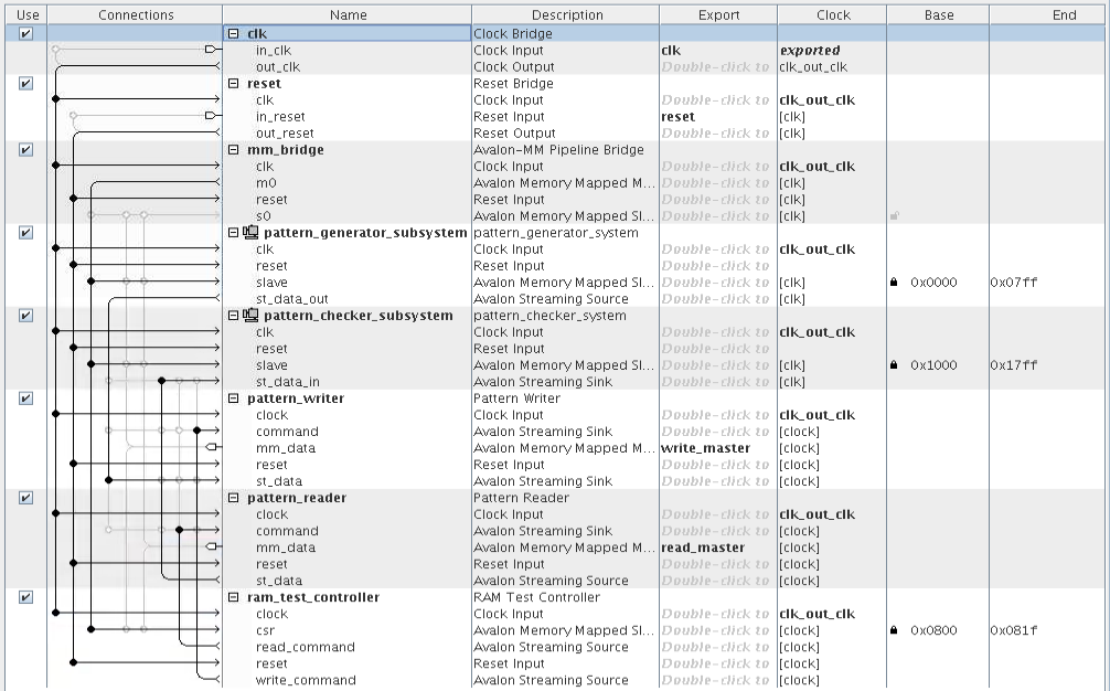
The following figure shows the completed system:Figure 32. Connections and Base Address Values for the memory_tester_sybsystem