Add Clock, Reset, and Avalon-MM components
Add Pre-Built Systems and Memory Test Microcore Components
Export Signals, Set Base Address Assignments, and Connect Memory Tester Interface Components
Resolve Interface Requirements and Value Mismatches
Replace the memory_tester_subsystem Generic Component
Synchronize IP Results
Add External Memory Interface
The next step is to add an Arria 10 External Memory Interfaces component and use presets to configure the parameters.
The Presets tab displays a list of applications consisting of different protocols and development kits. You can choose from the list and apply a pre-defined set of parameters to the selected IP components. The DDR4 component from the list of Presets implements a pre-configured module. Modify the following parameters to help meet timing for this design:
- Type external memory in the IP Catalog search box and double-click Arria 10 External Memory Interfaces to add it to the system.
- In the Arria 10 External Memory Interfaces parameter editor, select the Arria 10 GX FPGA Development Kit with DDR4 HILO from the Preset library and click Apply.
Figure 17. Arria 10 External Memory Interfaces Pane
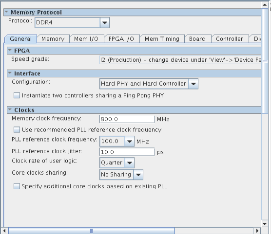
- In the Clocks section of the General tab, change Memory clock frequency to 800MHz and the PLL reference clock frequency value to 100MHz.
Figure 18. Memory Tab
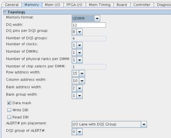
- Click the Memory tab and specify the following:
- Change the DQ width to 32.
- Turn off Read DBI.
- Select '0' from the DQS group of ALERT# list.
Figure 19. Diagnostics Tab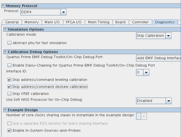
- Click the Diagnostics tab and specify the following:
- Turn on Skip address/command leveling calibration.
- Turn on Skip address/command deskew calibration.
- Click Finish.
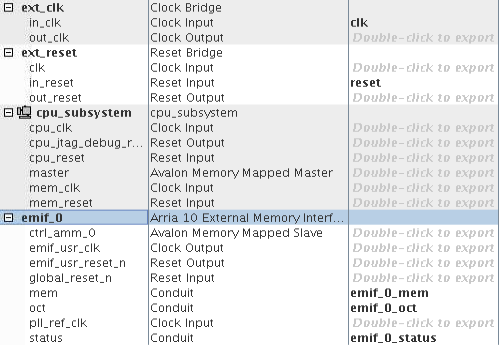
- Right-click the name of the top_system_emif_0 component and click Rename. Type emif_0.
- In the Export column, double-click the mem, oct, and status conduit interfaces and rename them emif_0_mem, emif_0_oct, and emif_0_status, respectively.
Figure 20. Export Names for emif_0 Signals