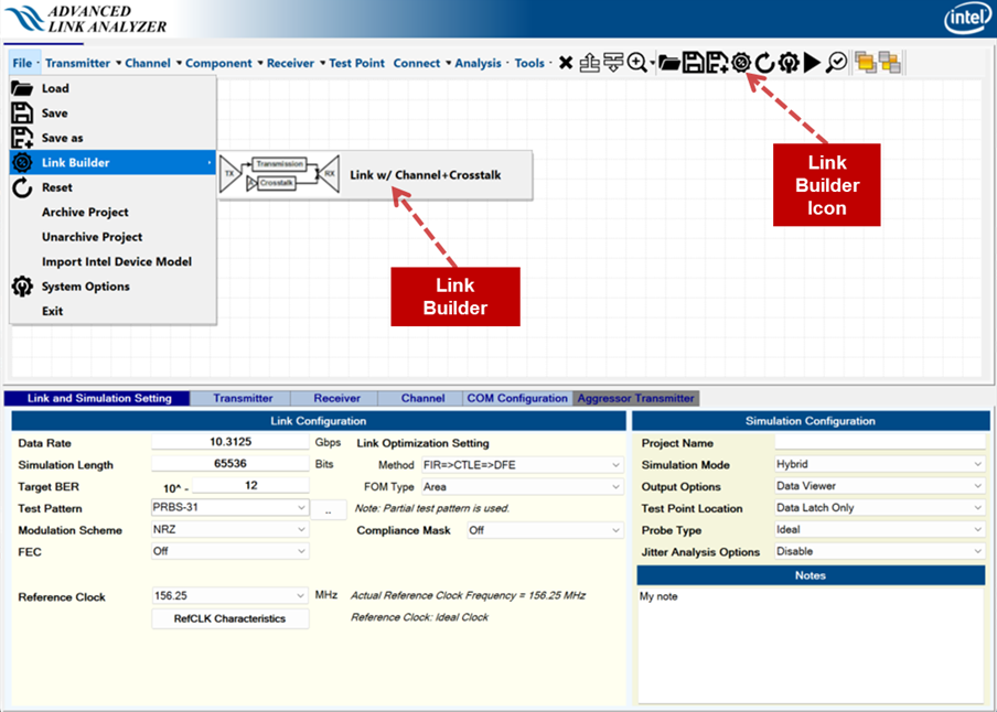
2.1.17. Link Builder
- From the File drop-down menu.
- Link Builder icon above the Link Designer in the GUI
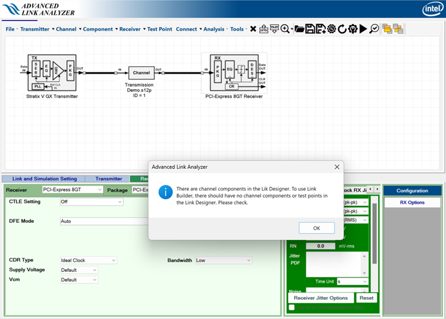
To build a link using the Link Builder, there must be no channel components (for example, transmission, FEXT, NEXT, test point, and so on) in the Link Designer. The Link Builder issues a warning when it identifies that there are channel components in the Link Designer, as shown in the following image:
The following image shows the Link Build user interface:
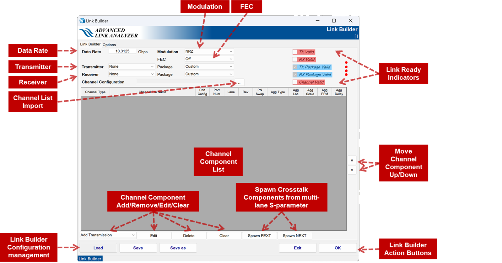
The following are the functions and uses of the Link Builder user interface:
- Data Rate: Specifies the data rate of the intended serial link in Gbps.
- Modulation: Specifies the modulation scheme of the intended serial link.
- FEC: Specifies the FEC scheme of the intended serial link.
- Transmitter: Specifies the transmitter type to be used in the link. The list of transmitter types is synchronized with the Intel® Advanced Link Analyzer installation and installed devices. The default package type is automatically selected when you select the transmitter type. You can select a different package type if desired.
Note:
Custom package type indicates one of the following:
- There is no transmitter package.
- The package is specified as part of the link schematic. For instance, you can add or specify a transmitter package component in the Link Builder’s Channel Component List.
- Receiver: Specify the receiver type to be used in the link. The list of receiver types is synchronized with the Intel® Advanced Link Analyzer installation and installed devices. The default package type is automatically selected when you select the receiver type. You can select a different package type if desired.
Note:
Custom package type indicates one of the following:
- There is no transmitter package.
- The package is specified as part of the link schematic. For instance, you can add or specify a transmitter package component in the Link Builder’s Channel Component List.
- Add Channel: The Add Transmission/FEXT/NEXT/Transmitter Package/Receiver Package drop-down menu instructs the Link Builder to open a file browser to select one or more channels with the channel type of transmission, FEXT, NEXT, transmitter package, or receiver package. The Channel Wizard shows when the channel files are successfully read to assist in configuring the channel component. The following are the rules and capabilities of the Link Builder for channel components:
- Link Builder supports cascading of transmission or victim signal path channel components. Therefore, you can add sub-components of the transmission or victim signal path to the Channel Component List. These sub-components are cascaded in the Link Designer with the order in the Channel Component List, where the first transmission channel component is connected to the transmitter.
- Link Builder does not support cascading of crosstalk (FEXT and NEXT) paths. The FEXT or NEXT channel components are considered end-to-end between the crosstalk aggressor and the victim receiver input ports.
- The placement of transmitter and receiver packages in the Channel Component List does not affect the serial link construction.
- Edit: Link Builder starts the Channel Wizard of the selected channel component in the Channel Component List. You can modify the channel configuration or select a different channel.
- Delete: Link Builder deletes the selected channel component in the Channel Component List.
- Clear: Link Builder clears and deletes all channel components in the Channel Component list.
- Spawn FEXT: If the transmission channel component existing in the Channel Component List is a multiple-lane S-parameter (snp file with n > 4), the Link Builder can automatically generate a list of far-end crosstalk (FEXT) channel components and add them to the Channel Component List. The following are the rules and operations of Spawn FEXT:
- Spawn FEXT only supports a single multiple-lane S-parameter. That is, there can be only one multiple-lane transmission channel component in the Channel Component List.
- Assume the transmission channel is a m-lane S-parameter (snp file with n = 4*m). The number of FEXT component channels generated is n/4-1.
- The FEXT channel components are configured such that the victim ports are the same as the transmission channel component. You can find the definition and port assignment of FEXT channel components in Channel Setting.
- The Spawn FEXT function automatically assigns frequency offset (in ppm) with an increment of 300 ppm to each FEXT channel component. You can further modify the characteristics of each FEXT channel component using the Edit button in the Link Builder or modify it later in the Link Designer.
- The Spawn FEXT function generates all valid FEXT channel components that meet the above rules. You are responsible for ensuring the FEXT component channels are correct and match the S-parameter’s generation or measurement conditions. You can freely delete the generated FEXT component channels (from the Channel Component List using the Delete button) when they do not match the above rules or they are not FEXT signal paths.
- After adding the FEXT channel components to the Channel Component List, you can modify each FEXT component’s configurations by clicking the Edit button in the Link Builder.
- Spawn NEXT: If the transmission channel component existing in the Channel Component List is a multiple-lane S-parameter (snp file with n > 4), the Link Builder can automatically generate a list of (NEXT) channel components and add them to the Channel Component List. The following are the rules and operations of the Spawn NEXT:
- Spawn NEXT only supports a single-multiple lane S-parameter. That is, there can be only one multiple-lane transmission channel component in the Channel Component List.
- Assume the transmission channel is a m-lane S-parameter (snp file with n = 4*m). The number of NEXT component channels generated is n/4-1.
- The NEXT channel components are configured such that the victim ports are the same as the transmission channel component. You can find the definition and port assignment of NEXT channel components in Channel Setting.
- The Spawn NEXT function automatically assigns frequency offset (in ppm) with the increment of 300 ppm to each NEXT channel component. You can further modify the characteristics of each NEXT channel component using the Edit button in the Link Builder or modify it later in the Link Designer.
- The Spawn NEXT function generates all valid NEXT channel components that meet the above rules. You are responsible for ensuring the NEXT component channels are correct and match the S-parameter’s generation or measurement conditions. You can freely delete the generated NEXT component channels (from the Channel Component List using the Delete button) when they do not match the above rules or they are not NEXT signal paths.
- After adding the NEXT channel components to the Channel Component List, you can modify each NEXT component’s configurations by clicking the Edit button in the Link Builder.
- Channel List Import: Imports Channel Component list from a file.
- The following is the channel list import file format:
Victim,num_of_victim_channel_components
File name of the first transmission/victim channel component,[victim/package configuration]
File name of the second transmission/victim channel component,[victim/package configuration]
.
.
.
FEXT,number_of_FEXTs
File name of the first FEXT channel component,[crosstalk configuration]
File name of the second FEXT channel component,[crosstalk configuration]
.
.
.
NEXT,number_of_NEXTs
File name of the first NEXT channel component,[crosstalk configuration]
File name of the second NEXT channel component,[crosstalk configuration]
.
.
.
TXPackage,1
File name of transmitter package,[victim/package configuration]
RXPackage,1
File name of receiver package,[victim/package configuration]
- [victim/package configuration] is a sequence of numbers separated by a comma:
<Port_Config>,<Number_of_Ports>,<Lane>,<Reverse> ,<PN_Swap>
- <Port_Config> is the S-parameter port configuration defined in Channel Setting.
- <Number_of_Ports> is the number of S-parameter ports.
- <Lane> is the lane number of differential pairs to be used in a multiple-lane S-parameter.
- <Reverse> : 1 indicates the S-parameter connected in the reverse direction as defined in Channel Setting.
- <PN_Swap> : 1 indicates the S-parameter connected with P and N ports swapped as defined in Channel Setting.
- [crosstalk configuration] is a sequence of numbers and string-separated by a comma:
<Port_Config>,<Number_of_Ports>,<Lane>,<Reverse>,<PN_Swap>,<Agg_Type>,<Agg_Location>,<Agg_Rel_Amplitude>,<Agg_Delay>,<Agg_Freq_Offset>
- <Port_Config> / <Number_of_Ports> / <Lane> / <Reverse> / <PN_Swap> : Same as in [victim/package configuration].
- <Agg_Type> is the type of aggressor as defined in Channel Setting where the types are Inline, Transmitter, and Aggressor.
- <Agg_Location> is the location of aggressors as defined in Channel Setting.
- <Agg_Rel_Amplitude> is the relative amplitude of the aggressor’s signal amplitude as defined in Channel Setting.
- <Agg_Delay> is aggressor delay in pico-second (ps) as defined in Channel Setting.
- <Agg_Freq_Offset> is aggressor frequency offset in ppm as defined in Channel Setting.
Note: If there is no FEXT or NEXT, include the FEXT,0 or NEXT,0 text in the channel list file. You can find an example of the channel import file in the following image: - The following is the channel list import file format:
- Move Up: The selected channel component moves up by one place when you click the Move Up button.
- Move Down: The selected channel component moves down by one place when you click the Move Down button.
- Link Ready Indicators: There are five link-readiness checks (Link Ready Indicators) in the Link Builder. These indicators help you determine whether the Link Builder has sufficient and correct information and link components to construct a serial link.
- TX Valid: This indicator turns blue when you select a transmitter. The Link Builder allows the transmitter to be the existing transmitter assigned before starting the Link Builder. You can change the transmitter type in Link Builder. If you do not assign the transmitter, the indicator turns red.
- RX Valid: This indicator turns blue when you select a receiver. The Link Builder allows the receiver to be the existing receiver assigned before starting the Link Builder. You can change the receiver type in the Link Builder. If you do not assign the receiver, the indicator turns red.
- TX Package Valid: This indicator turns blue when the transmitter package type and configuration are valid. The existence of a transmitter package is optional. When a transmitter package exists, it must be unique in the link. When the Link Builder detects that there are more than one transmitter packages, the indicator turns red.
- RX Package Valid: This indicator turns blue when the receiver package type and configuration are valid. The existence of a receiver package is optional. When a transmitter package exists, it must be unique in the link. When the Link Builder detects that there are more than one receiver packages, the indicator turns red.
- Channel Valid: This indicator turns blue when channel components exist and are valid. A valid channel configuration means that there is a transmission/victim signal path from a transmitter to a receiver and optionally, there are valid FEXT and/or NEXT aggressor signal paths.
- OK: When you click the OK button, the Link Builder first checks if the Link Ready Indicators are all blue and checked. If the link-ready checking fails, a warning message appears. You can follow the status of the link Indicators as well as the error message to correct or modify the Link Builder configuration. When the link-ready checking is complete and successful, the Link Builder closes, and a serial link is constructed in the Link Designer.
- You can modify the constructed link similar to other links created natively in the Link Designer.
- You are responsible for completing the remaining link configurations, such as device corners, package length, test pattern selection, transmitter/receiver configurations, and so on, before performing link simulations.
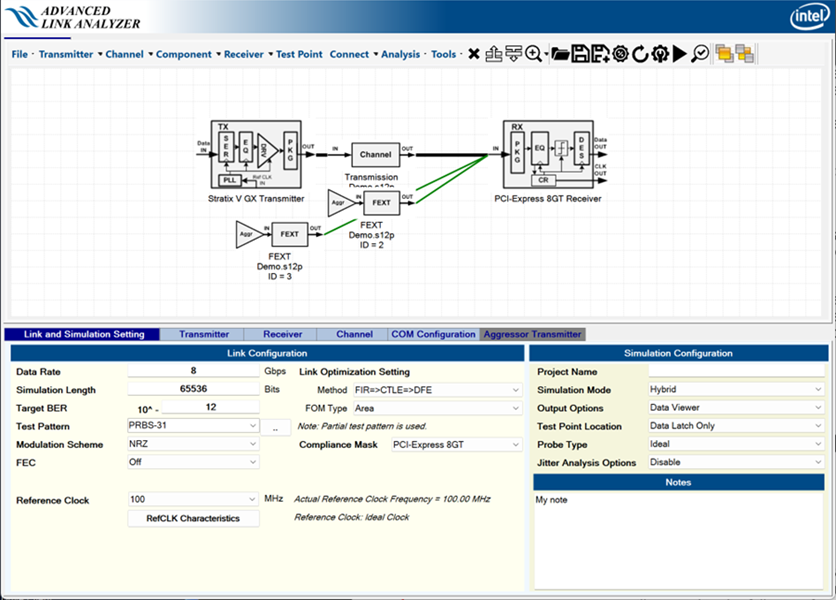
For example, you can construct a serial link between a Stratix® V GX transmitter and a PCI Express* Gen 3 reference receiver with a 12-port (3-lanes, S-parameter file Demo.s12p) running at 8 Gbps and NRZ modulation scheme. The victim signal path is Lane 2, while Lane 1 and Lane 3 carry FEXT signals. The Link Build configuration automatically generates links as illustrated in the following images:
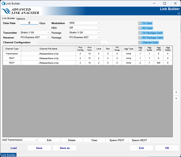
You can also create a channel import file to configure the Channel Component List as shown in Link Builder Configuration Example. The channel import file will be:
Victim,1
..\Release\Demo.s12p,2,12,2,0,0
FEXT,2
..\Release\Demo.s12p,2,12,2,0,0,Inline,1,1.000000,0.000000,0.000000
..\Release\Demo.s12p,2,12,2,0,0,Inline,2,1.000000,0.000000,300.000000
NEXT,0
- Exit: Exits the Link Builder without constructing a link in the Link Designer.
- Load/Save/Save as: Click these buttons to load or save Link Builder configurations.