2.1.6. Channel Setting
The channel connects the transmitter and the receiver. It contains transmission media such as PCB traces, connectors, backplanes, cables, and device packages. A channel is a combination of numerous components described by channel models. Intel® Advanced Link Analyzer’s channel processing engine first interprets the channel models and then connects and cascades channels to construct one channel component for link simulations.
Intel® Advanced Link Analyzer supports single-ended Touchstone 1.0 and selected types of Touchstone 2.0 S-parameter channel models. It can access and process n-port S-parameters and extract transmission responses and crosstalk responses. After successfully extracting the channel characteristics, it performs differential-pair channel cascading for subsequent link simulation.
Intel® Advanced Link Analyzer supports key Touchstone 2.0 features for high-speed serial link simulations. Highlights of Touchstone 2.0 support in the current version include:
- Touchstone 2.0 headers.
- Matrix format is supported.
- Mixed-mode S-parameter is partially supported. Intel® Advanced Link Analyzer currently requires the whole mixed-mode S-parameter or only the differential-input-differential-output response to be present. This means that either all sections, which include differential-differential, differential-common, common-differential, and common-common sections of all ports and differential pairs are present, or only the differential-differential section is present. Partial mixed-mode S-parameters are not allowed.
- S-parameter files with an odd number of ports or odd number of differential pairs are not supported.
- Noise data and associated data formats can be included in the file but are not processed.
- Arbitrary port reference is not supported.
Intel® Advanced Link Analyzer supports Channel Designer components such as stripline, microstrip, coax, RLGC, ideal transmission line, coupled stripline, and coupled microstrip. When you select a Channel Designer component, you can choose different configurations in the associated channel designer GUI. PCB stackup is also supported, in which you can enter PCB substrate and stackup information. Supported channel models, which include stripline, microstrip, coupled stripline, and coupled microstrip, can utilize any available PCB stackup dataset in the design. Multiple PCB stackup dataset is supported in Intel® Advanced Link Analyzer. Refer to the Intel® Advanced Link Analyzer Channel Designer section for detailed information about the usage of channel designer components.
Intel® Advanced Link Analyzer implements the Link Designer, which allows you to graphically construct the communication link. In the following figure, the Channel List shows a channel construction example with one transmission channel (such as a loss channel or a victim channel) and two crosstalk channels.
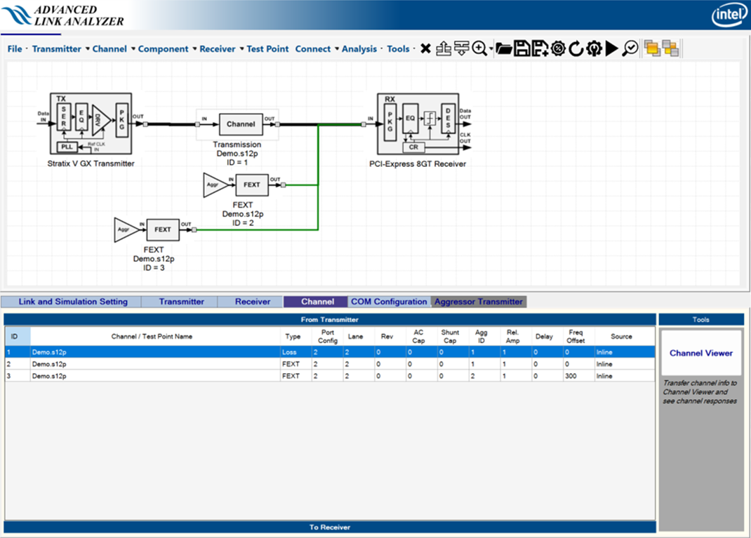
An S-parameter channel component such as a connector, cable, or backplane can be described by the following parameters or information:
- ID—Sequence or location of the channel component. The top channel is connected to the transmitter and the bottom channel is connected to the receiver.
Note: Embedded package models (such as Package models for Intel devices and PCI Express* Gen3 devices) are not shown in the channel list or Link Designer.
- Channel Name—An S-parameter file that describes the channel component. The S-parameter can be 4-port, 8-port, 12-port, 16-port, and so forth. When your cursor hovers on a channel list, a tooltip shows the S-parameter file location. This information is useful if you share Intel® Advanced Link Analyzer configuration files.
- Type—Specify the type of channel characteristics to be used in the link simulation. The type of channel characteristics can be insertion loss (Loss), far-end crosstalk (FEXT), or near-end crosstalk (NEXT). You can change the channel (or channel type) by selecting the channel from the Link Designer using the Channel Wizard.
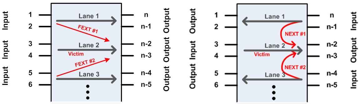
- Port Configuration—Depending on the S-parameter measurement condition, the port configuration can be one of the following types. Use the Channel Wizard to change the port configuration of an S-parameter.
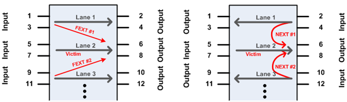
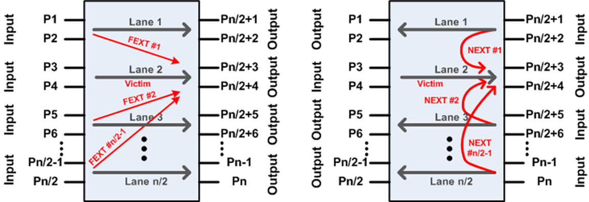
If the S-parameter file is not Type 1, Type 2, or Type 3, you can use the Custom option in the Channel Wizard’s Port Config pull-down menu, as shown in the following figure. When a Custom port configuration is selected in the Channel Wizard, a text box named Port Map appears below the port configuration figure (one of the configurations in the above figure). Enter the port numbers in the sequence [P1, P2, P3, …Pn], where n is the number of ports, as illustrated in the figure above that matches the selected S-parameter model. In the figure below, the Port Map sequence 1 3 2 4 corresponds to a 4-port (n=4) S-parameter model with port configuration Type 2 where P1=1, P3=Pn/2+1=2, P2=3, and P4=Pn/2+2=4. When a custom port configuration is assigned to an S-parameter model, it is displayed as port configuration Type 4 in the channel table.
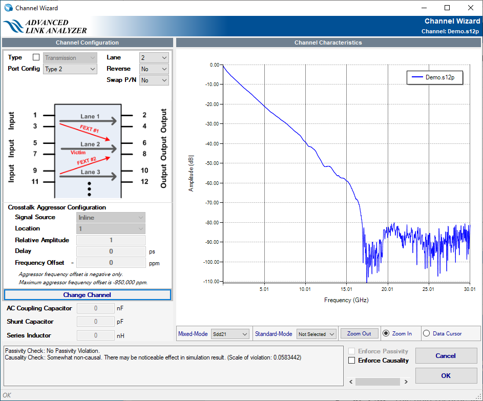
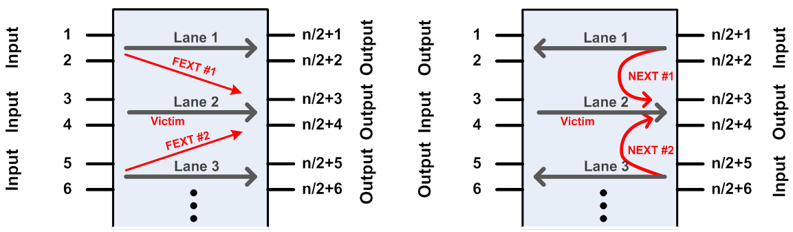
- Lane—This field lists the channel lane ID number. For channel lane S-parameters that are 8-port and above, a channel lane must be chosen for link simulations. For example, the above figures show a 12-port 3-lane S-parameter. After loading the channel file, Intel® Advanced Link Analyzer assigns the center lane as the default simulating channel (or victim channel for crosstalk simulations). Use the Channel Wizard to change the lane ID. For 2-port or 4-port S-parameter models, the lane ID is ignored.
- Reverse—This field indicates whether the channel signal flow direction is to be reversed. This is generally used for the device package model when you want to make sure transmitter and receiver devices are connected to the die side of the package S-parameter model. Refer to the S-parameter comment section for S-parameter signal flow configuration.
- Swap P/N—This field indicates whether P-port and N-port of the S-parameter are swapped.
- AC Cap—This field records AC coupling capacitor value in nF (nano-Farad, 10-9 F).
- Shunt Cap—This field records shunt capacitance value in pF (pico-Farad, 10-12 F).
A crosstalk aggressor has the following parameters:
- Source—Each crosstalk aggressor can be of Inline, Transmitter, or Aggressor type.
- With an inline aggressor, the input to the crosstalk channel is the input waveform at the last transmission/victim channel segment.
- With a transmitter aggressor, the aggressor waveform is the same as the victim transmitter with the above aggressor effects, such as frequency offset, delay, and relative amplitude, applied.
- If the aggressor type is “Aggressor X”, the aggressor is modeled by the Xth aggressor type as shown in the Aggressor Transmitter tab (refer to the Crosstalk Aggressor Transmitter Setting section).
The following figure shows the three crosstalk aggressor transmitter types. Inline aggressor means the signal feeding into the crosstalk channel comes from the immediate victim channel in parallel with the XTLK channel (as shown in the red dotted arrow line). TX Aggressor means that, regardless of where the XTLK channel is located, this XTLK always uses the VICTIM TX output as its signal source (shown in the green dotted line). The Individual Aggressor TX is similar to the Victim TX Aggressor, but it can be generated separately.
Figure 71. Crosstalk Aggressor Types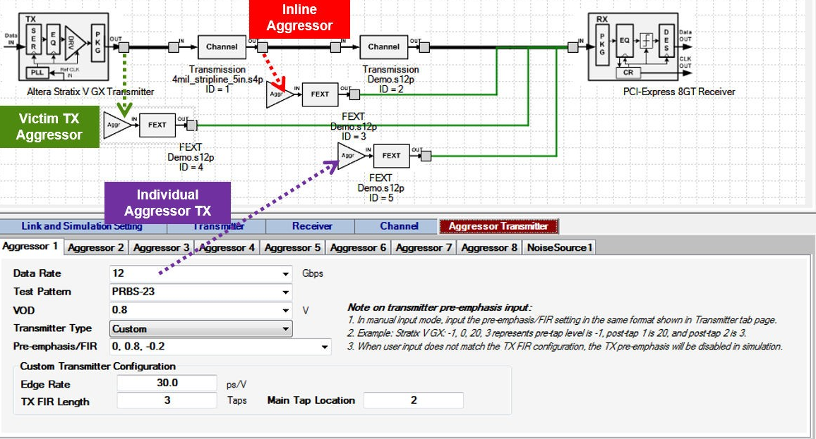
- Location—For multiple channel/lane S-parameters simulating crosstalk effects, you must specify the aggressor location. For example, the above figures show four possible crosstalk configurations from a 12-port S-parameter model. Use the Aggressor Location menu in the Channel Wizard to change the aggressor location. The Aggressor ID field is ignored for a victim channel (Loss type).
Note: The Aggressor ID index excludes victim lanes. For example, in a 12-port S-parameter, there are three lanes. If the middle lane (Lane ID 2) is a victim lane, the two aggressor channels have Aggressor ID 1 and 2, not 1 and 3.
- Relative Amplitude—Each crosstalk aggressor can have different aggressor amplitude relative to its original amplitude. The default value for aggressor is 1.0, which indicates the aggressor has its original amplitude. The Aggressor ID field is ignored for a victim channel (Loss type).
- Delay—Each crosstalk aggressor can have individual delay or time offset. The delay is input in picoseconds (ps, 10-12 second). Positive values in aggressor delay indicate the aggressor is lagging behind the victim waveform. Negative values indicate the aggressor is ahead of the victim signal waveform. The Aggressor ID field is ignored for a victim channel (Loss type).
- Frequency Offset—Each crosstalk aggressor can run on an offset frequency compared to the victim channel’s transmitter. The frequency offset is given in negative ppm (parts per million). The maximum frequency is –950,000 ppm.
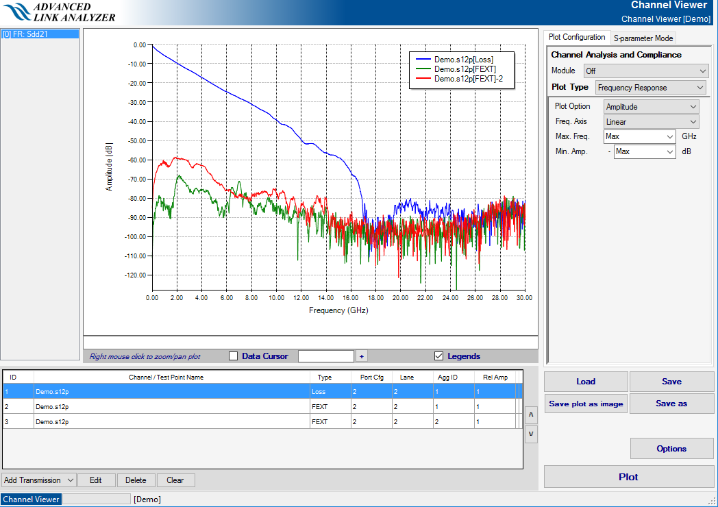
The Channel Viewer button is a convenient way of observing channel characteristics in the current channel list. Click Channel Viewer to transfer the channels to a new Channel Viewer window. You can then observe various parts of channel characteristics in either frequency- or time-domain. Use the Intel® Advanced Link Analyzer Channel Viewer to view cascaded channel characteristics if multiple channel components are used in the victim signal path. The following figure illustrates the Channel Viewer plot of the channel construct shown in Intel® Advanced Link Analyzer Channel Viewer Example.
Refer to the Tutorial: PCI Express* 8GT chapter for step-by-step channel setup instructions.
Automatic S-parameter Configuration Check (ASCC)
Intel® Advanced Link Analyzer uses a proprietary Automatic S-parameter Configuration Checker (ASCC) to help you set and connect the S-parameter in the channel chain. With ASCC, Intel® Advanced Link Analyzer inspects the S-parameter model and determines the port number and port configuration. ASCC also selects the middle lane as the victim channel (insertion loss channel) and sets the Lane and Aggressor pull-down menus for user configuration. Channel configuration information is saved individually for each channel. Therefore, S-parameters with different port numbers, port configurations, or both can be mixed and cascaded in Intel® Advanced Link Analyzer.