2.1.3.4. IBIS-AMI Transmitter Configuration
- Package—Package models are required in all IBIS models. Intel® Advanced Link Analyzer includes the IBIS package model in the simulation by default. You can choose other package models by changing the Package selection to Custom and specifying the external package model (Channel type Package) as a channel component.
Note: Make sure there is only one package model for the IBIS-AMI transmitter. Use either package type IBIS-AMI or package type Custom with external package model in the schematic. Simulation errors may occur if you have more than one transmitter package model in the link.
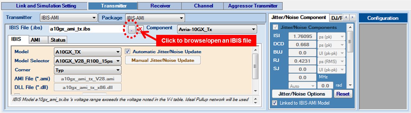
- IBIS Files—Click the file open button next to the IBIS File text box to select an IBIS model file. Intel® Advanced Link Analyzer scans through the IBIS file and allocates all available transmitter components and models. If Intel® Advanced Link Analyzer encounters the following issues in opening or interpreting the IBIS-AMI model, a warning message is displayed.
- No transmitter component or model can be located.
- The DLL for the computer platform cannot be located. The IBIS-AMI model is platform dependent. For example, a 32-bit DLL is required to simulate in a 32-bit link simulator and a 64-bit DLL is required to simulate in a 64-bit simulator. A 32-bit DLL cannot simulate in a 64-bit DLL simulator.
- The DLL occupies too much memory and Intel® Advanced Link Analyzer was not able to load it. However, Intel® Advanced Link Analyzer might be able to run the simulation with such a DLL because of memory allocation differences in the Intel® Advanced Link Analyzer GUI and the simulation engine.
- Component—Select an IBIS component from the IBIS model.
- IBIS tab—The IBIS tab shows the following configuration parameters:
- Model—Select a device model within a component of an IBIS model.
- Model Selector—Select a model from the model selector list.
- Corner—Select the corner type of a device model. The choices are Typ, Min, and Max.
- AMI File—Shows the AMI file specified in the IBIS model.
Note: Intel® Advanced Link Analyzer currently only supports device models with AMI modeling components.
- DLL File—Shows the DLL file specified in the IBIS model.
- Use External Termination—Indicates that an external termination is used in the simulation. The external termination (single-ended) is specified in the text box on the right. The default setting is not using external termination and the default external termination (if applicable) is 50 ohms (single-ended).
- Use Rising/Falling Waveform—If rising/falling waveforms are available in the IBIS model, the rising/falling waveforms are used to model the transmitter by default. If you turn off this option, ramp data (in the IBIS model) is used in the simulation.
- Automatic Jitter/Noise Update—Allows automatic jitter/noise updates from the IBIS-AMI model (available for models which are compliant with IBIS-AMI 6.0 and later).
Note: If you experience unexpected long delay when loading an IBIS-AMI model, you can disable the Automatic Jitter/Noise Update by turning it off. It was seen that certain IBIS-AMI models perform computation-intensive functions (such as equalization adaptation) during the jitter/noise retrieval. You can still retrieve jitter/noise numbers by manually clicking the Manual Jitter/Noise Update button.
- Manual Jitter/Noise Update—When the Automatic Jitter/Noise Update option is disabled, turning on this option allows you to manually update the jitter/noise figures from the IBIS-AMI model (available for models which are compliant with IBIS-AMI 6.0 and later).
- DLL_Path—Specify a folder or path name where the supporting files of an IBIS-AMI model are stored. Refer to the IBIS standards for details.
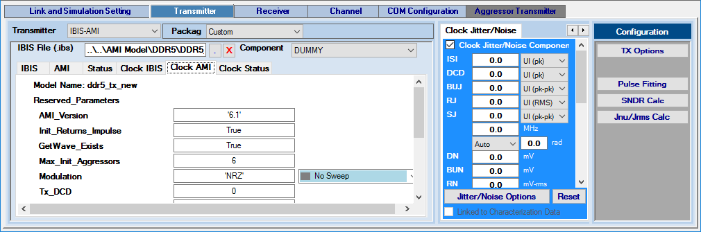
AMI tab
The AMI tab shows the following AMI configuration parameters.
- Model Name—IBIS-AMI model name
- Reserved Parameters:
- The IBIS-AMI reserved parameters are shown. The reserved parameters are meant for the Intel® Advanced Link Analyzer simulation configuration.
- IBIS-AMI Rev 5.0 and 6.0 jitter parameters (Tx_Jitter) are extracted and automatically set in the Transmitter's Jitter/Noise window with the interpretation shown in the following table:
Table 11. IBIS-AMI Jitter Parameters IBIS-AMI Tx_Jitter Parameter
Intel® Advanced Link Analyzer Interpretation
(Tx_Jitter (Usage Info)(Type Float)
(Format Gaussian <mean> <sigma>))
DJ = <mean> UI (pk) or ps (pk). Uniform distribution
RJ = <sigma> UI (RMS) or ps (RMS)
(Tx_Jitter (Usage Info)(Type Float)
(Format Dual-Dirac <mean> <mean> <sigma>))
DJ = (<mean> + <mean>)/2 UI (pk) or ps (pk). Dual-Dirac distribution
RJ = <sigma> UI (RMS) or ps (RMS)
(Tx_Jitter (Usage Info)(Type Float)
(Format DjRj < minDj > < maxDj > <sigma>))
DJ = <maxDJ> UI (pk) or ps (pk). Uniform distribution
RJ = <sigma> UI (RMS) or ps (RMS)
(Tx_Jitter (Usage Info)(Type Integer Float/UI Float)
(Format Table (Labels Row_No Time or UI Probability)
(-5 -5e-12 1e-10)
(-4 -4e-12 3e-7) … ))
Refer to the transmitter jitter description in the Jitter/Noise Component section.
IBIS-AMI Tx_DCD Parameter
Intel® Advanced Link Analyzer Interpretation
(Tx_DCD (Usage Info)(Type Float)
(Format Range <typ> <min> <max>))
DCD = <typ or min or max based on corner selection> UI (pk) or ps (pk), Clock jitter distribution
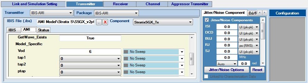
- Model Specific Parameters—This section lists all the model specific parameters that the IBIS-AMI model provides. You can use their selections or specify parameters for the simulation.
Figure 35. Transmitter IBIS-AMI Parameter Type Designation for Link Optimization
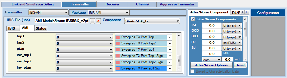
Intel® Advanced Link Analyzer supports link optimization with IBIS-AMI transmitter models. On the left are the model specific parameters. For each parameter that Intel® Advanced Link Analyzer determines is sweepable, a pull-down menu allows you to assign the transmitter parameters. The types of transmitter parameters are as follows:
- No Sweep—No sweeping or link optimization is performed
- Sweep— Intel® Advanced Link Analyzer sweeps or performs link optimization using available options provided by the IBIS-AMI model
- Sweep as TX Main Tap— Intel® Advanced Link Analyzer treats this parameter as the main cursor tap of transmitter equalizer in link optimization
- Sweep as TX Main Tap Sign— Intel® Advanced Link Analyzer treats this parameter as the sign bit of the main cursor tap in link optimization
- Sweep as TX Post-Tap n— Intel® Advanced Link Analyzer treats this parameter as the n-th post-cursor tap of transmitter equalizer in link optimization
- Sweep as TX Post-Tap n Sign— Intel® Advanced Link Analyzer treats this parameter as the sign bit of the n-th post-cursor tap in link optimization
- Sweep as TX Pre-Tap n— Intel® Advanced Link Analyzer treats this parameter as the n-th pre-cursor tap of transmitter equalizer in link optimization
- Sweep as TX Pre-Tap n Sign— Intel® Advanced Link Analyzer treats this parameter as the sign bit of the n-th pre-cursor tap in link optimization
With the information provided in the IBIS-AMI model and parameter type selections, Intel® Advanced Link Analyzer determines the link optimization approach and conducts the simulation. All link optimization methods are supported with IBIS-AMI transmitter models, but generally the CTLE=>FIR=>DFE and CTLE=>FIR+DFE methods are more efficient (in terms of simulation time) and effective. If you cannot determine the nature of the model specific parameters, consult with the IBIS-AMI vendors. An example of transmitter IBIS-AMI parameter type designations is shown in the above figure.
For Intel devices, link optimization is further and better supported using Intel® Advanced Link Analyzer IBIS-AMI Wrapper Technology. Therefore, Intel recommends installing and using the IBIS-AMI wrapper for all supported devices.
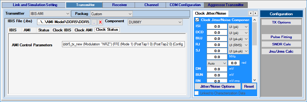
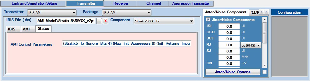
Status tab
The Status tab shows the parameters that are fed into the IBIS-AMI model for simulations.
Consider the following for the IBIS-AMI transmitter modeling support in Intel® Advanced Link Analyzer:
- Intel® Advanced Link Analyzer only supports the IBIS model with an AMI component. An IBIS model without an AMI component is not simulated.
- Transmitter PLL is not supported when the IBIS-AMI transmitter is selected.
- Intel® Advanced Link Analyzer supports IBIS-AMI transmitter models with the on-die S-parameter model (IBIS BIRD 158.3) using the txic, Tstonefile, or Ts4file IBIS-AMI keyword. When Intel® Advanced Link Analyzer detects the txic, Tstonefile, or Ts4file keyword, the Channel Wizard helps you determine the on-die S-parameter configuration.
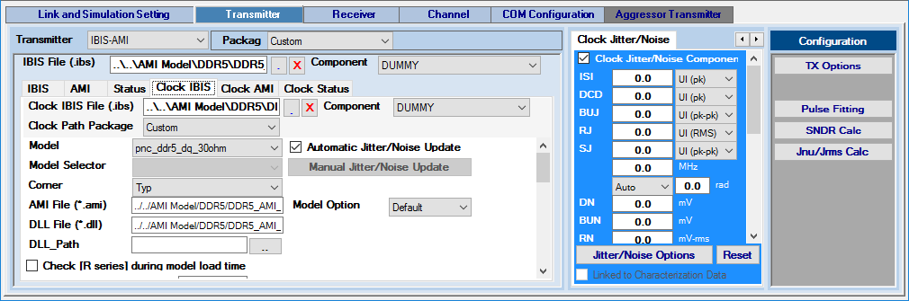
Clock Path IBIS-AMI Transmitter
When you select a clock path IBIS-AMI transmitter and place it in the design space, you can find the following group of tab pages next to the data path IBIS-AMI transmitter tab pages: Clock IBIS, Clock AMI, and Clock Status. The user interface structure is similar to the data path IBIS-AMI transmitter’s structure. The only exception is that there is an option to choose a clock path package model. Also, you can configure the jitter/noise of clock path transmitter by using the clock path jitter/noise tab page as described in Jitter/Noise Component.