A newer version of this document is available. Customers should click here to go to the newest version.
2.1.8. Crosstalk Aggressor Transmitter Setting
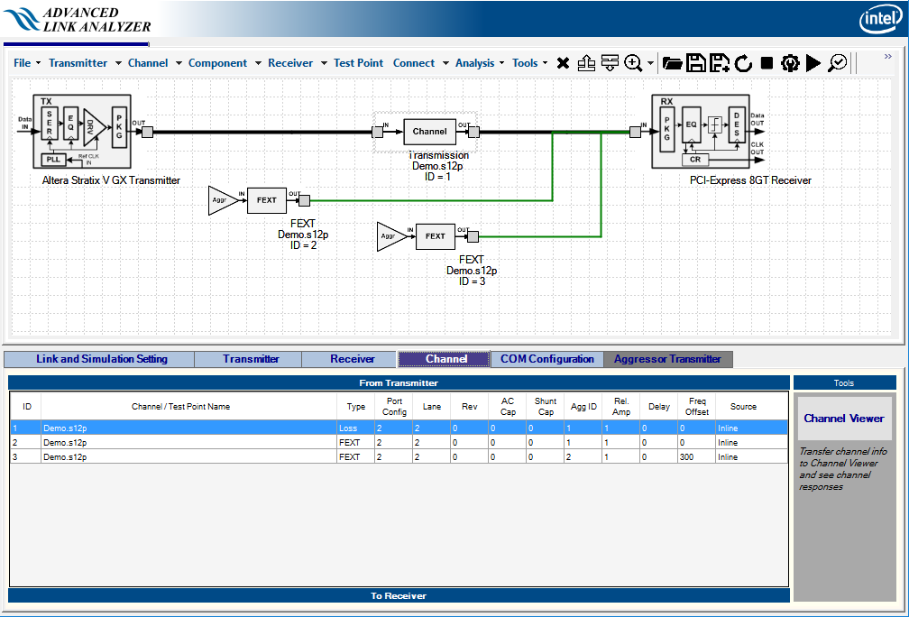
Aggressor transmitter configurations allow you to configure crosstalk aggressors individually with different transmitter types, pre-emphasis settings, amplitudes, data rates, and so forth. The following figure shows a 2-aggressor link with three different aggressor transmitters.
Follow the steps described in the previous section to set up a link with crosstalk channels. In the Channel Wizard window, in the Signal Source menu of the Crosstalk Aggressor panel, select the Inline, Transmitter, or one of the eight available Aggressor types.
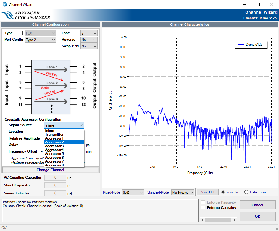
Advanced Link Analyzer supports up to eight individual crosstalk aggressor transmitters. However, a crosstalk aggressor transmitter can be shared among crosstalk channels. By combining the aggressor relative amplitude, frequency offset, and delay setting, Advanced Link Analyzer can generate a variety of crosstalk aggressor signal sources.
After completing the configuration in the Channel Wizard, go to the Advanced Link Analyzer GUI and select the Aggressor Transmitter tab.
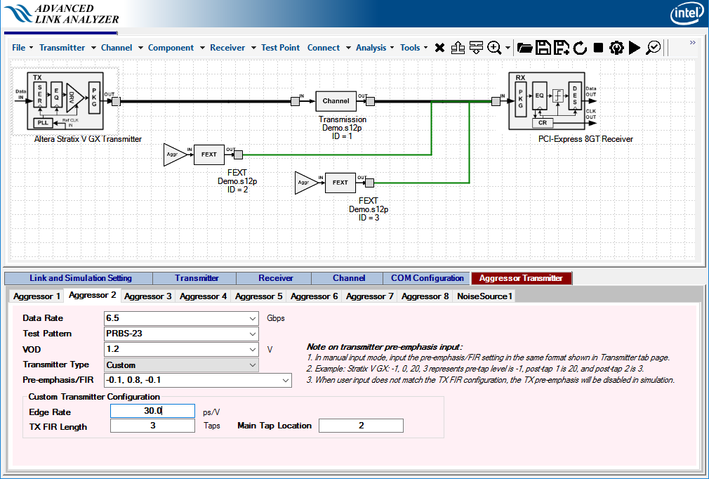
Within the Aggressor Transmitter tab, there are eight aggressor types associated with the aggressor types in the Channel Wizard’s Signal Source menu. Each aggressor can be configured as follows:
- Data Rate—Data rate of the selected aggressor transmitter in Gbps.
- Test Pattern—Aggressor transmitter’s test pattern. Advanced Link Analyzer supports the following test patterns:
- Same as victim TX
- PRBS-7, PRBS-9, PRBS-11, PRBS-15, PRBS-23, PRBS-31
- VOD—Differential output voltage of the aggressor transmitter in volts.
- Transmitter Type—Aggressor transmitter can be one of the following transmitter types:
- Same as victim TX
- Stratix® V GX
- Arria® V GZ
- Stratix® V GT
- Custom
- Pre-emphasis / FIR—Pre-emphasis or FIR setting of the aggressor transmitter. You can set it to be the same as the victim TX or you can type in the setting.
Note:
- In manual pre-emphasis/FIR input mode, the pre-emphasis/FIR setting must be in the same format as used in the Transmitter tab. This does not mean that the aggressor transmitter must be the same type as the victim transmitter, but that the pre-emphasis setting format must be in the format as if it is a victim transmitter. For example, if the aggressor transmitter type is Intel Stratix® V GX, the pre-emphasis/FIR setting is in a list of TX-FIR levels such as -1, 0, 20, 3, where -1 is the pre-tap 1 value, 20 is the post-tap 1 value, and 3 is the post-tap 2 value. The main tap can be any value, because Advanced Link Analyzer determines the main tap's value based on the values of other FIR taps.
- If you input TX pre-emphasis /FIR, which is invalid for the selected transmitter type, then pre-emphasis/FIR is disabled.
If the transmitter type is Custom, the following parameters are also used:
- Edge Rate—Advanced Link Analyzer generates a transmitter output waveform with the specified edge rate. Edge rate is in the format of ps/Volt.
- TX-FIR Length—Length of TX-FIR for custom aggressor transmitter.
- Main-Tap Location—Location of main tap of aggressor transmitter.
The example shown in Aggressor Transmitter Tab indicates an aggressor transmitter, which is a custom transmitter type, running at 6.5 Gbps with the PRBS-23 test pattern and a VOD of 1.2 V. The TX FIR coefficients are [-0.1, 0.8, -0.1] with a TX-FIR length of 3 and the main tap is at 2nd tap. According to the link configuration shown in Aggressor Transmitter with Two Individual Aggressor Transmitters, this aggressor transmitter is associated with Crosstalk (FEXT) channel ID = 2.