2.3.3.2. Plot Configuration Panel
The Channel Analysis and Compliance Module menu controls the channel characteristics plotting modes:
- Off—Channel Viewer plots channel characteristics as directed by your configuration. In the mode, you can plot frequency responses, impulse responses, and single bit responses. This is the default Channel Viewer plotting mode.
- Channel Analysis—Channel Viewer performs a sequence of operations to calculate and show channel performance in terms of ILD (Insertion Loss Deviation), RL (Return Loss), ICR (Insertion Loss to Crosstalk Ratio), and Crosstalk Noise calculations. This allows you to determine the wellness of the channels.
Channel Analysis supports customizable compliance masks for IL, ILD, RL, ICN, and ICR. This feature can be used to perform custom channel compliance checks for proprietary links. When Custom is selected, you can enter channel compliance mask definition in each text box with the format: frequency (Hz) and amplitude (dB). You can also load a predefined custom channel compliance mask definition from a file.
- 10GBASE-KR Channel Compliance—Channel Viewer performs channel compliance checks per 10 Gbps Ethernet over backplane (IEEE 802.3ap, 10GBASE-KR) standards.
- OIF CEI-28G-SR 3.0 Channel Compliance—Channel Viewer performs channel compliance checks per OIF CEI-28G-SR 3.0 standards.
- OIF CEI-25G-LR 3.0 Channel Compliance—Channel Viewer performs channel compliance checks per OIF CEI-25G-LR standards.
- OIF CEI-28G-MR 3.1 Channel Compliance—Channel Viewer performs channel compliance checks per OIF CEI-28G-MR standards.
- COM 802.3 100GBASE-CR4 Channel Compliance—Channel viewer performs channel compliance checks per IEEE 802.3 100GBASE-CR4 standards.
- COM 802.3 CAUI-4 C2C Channel Compliance Channel viewer performs channel compliance checks per IEEE 802.3 CAUI-4 C2C standards.
- COM 802.3 100GBASE-KP4 Channel Compliance—Channel viewer performs channel compliance checks per IEEE 802.3 100GBASE-KP4 standards.
- COM 802.3 100GBASE-KR4 Channel Compliance—Channel viewer performs channel compliance checks per IEEE 802.3 100GBASE-KR4 standards.
- COM Analysis—Channel Viewer performs a sequence of operations to calculate and show channel performance based on COM (Channel Operating margin) methodology. Channel Viewer allows you to customize parameters that configure COM calculation.
- COM 802.3 CAUI-4 C2C Channel Compliance—Channel viewer performs channel compliance checks per IEEE 802.3 CAUI-4 C2C standards.
- COM 802.3 200GAUI-4 Channel Compliance—Channel viewer performs channel compliance checks per IEEE 802.3 200GAUI-4 standards.
- COM 802.3 400GAUI-8 Channel Compliance—Channel viewer performs channel compliance checks per IEEE 802.3 400GAUI-8 standards.
- COM 802.3 200GAUI-4 C2M Channel Compliance—Channel viewer performs channel compliance checks per IEEE 802.3 200GAUI-4 C2M standards.
- COM 802.3 400GAUI-8 C2M Channel Compliance—Channel viewer performs channel compliance checks per IEEE 802.3 400GAUI-8 C2M standards.
- COM 802.3 200GBASE-CR4 Channel Compliance—Channel viewer performs channel compliance checks per IEEE 802.3 200GBASE-CR4 standards.
- COM 802.3 100GBASE-CR2 Channel Compliance—Channel viewer performs channel compliance checks per IEEE 802.3 100GBASE-CR2 standards.
- COM 802.3 50GBASE-CR Channel Compliance—Channel viewer performs channel compliance checks per IEEE 802.3 50GBASE-CR standards.
- COM 802.3 200GBASE-KR4 Channel Compliance—Channel viewer performs channel compliance checks per IEEE 802.3 200GBASE-KR4 standards.
- COM 802.3 100GBASE-KR2 Channel Compliance—Channel viewer performs channel compliance checks per IEEE 802.3 100GBASE-KR2 standards.
- COM 802.3 50GBASE-KR Channel Compliance—Channel viewer performs channel compliance checks per IEEE 802.3 50GBASE-KR standards.
- COM OIF-CEI-56G-LR Channel Compliance—Channel viewer performs channel compliance checks per OIF-CEI-56G-LR standards.
- COM OIF-CEI-56G-MR Channel Compliance—Channel viewer performs channel compliance checks per OIF-CEI-56G-MR standards.
- ERL-CH 802.3 50GBASE-KR Effective Return Loss (ERL) Compliance—Channel viewer performs channel return loss compliance checks per IEEE 802.3 50GBASE-KR standards.
- ERL-CH 802.3 100GBASE-KR2 ERL Compliance—Channel viewer performs channel return loss compliance checks per IEEE 802.3 100GBASE-KR2 standards.
- ERL-CH 802.3 200GBASE-KR4 ERL Compliance—Channel viewer performs channel return loss compliance checks per IEEE 802.3 200GBASE-KR4 standards.
- ERL-CH 802.3 50GBASE-CR ERL Compliance—Channel viewer performs channel return loss compliance checks per IEEE 802.3 50GBASE-CR standards.
- ERL-CH 802.3 100GBASE-CR2 ERL Compliance—Channel viewer performs channel return loss compliance checks per IEEE 802.3 100GBASE-CR2 standards.
- ERL-CH 802.3 200GBASE-CR4 ERL Compliance—Channel viewer performs channel return loss compliance checks per IEEE 802.3 200GBASE-CR4 standards.
- ERL-SI 802.3 50GBASE-KR ERL Compliance—Channel viewer performs transmitter and receiver return loss compliance checks per IEEE 802.3 50GBASE-KR standards.
- ERL-SI 802.3 100GBASE-KR2 ERL Compliance—Channel viewer performs transmitter and receiver return loss compliance checks per IEEE 802.3 100GBASE-KR2 standards.
- ERL-SI 802.3 200GBASE-KR4 ERL Compliance—Channel viewer performs transmitter and receiver return loss compliance checks per IEEE 802.3 200GBASE-KR4 standards.
- ERL-SI-RX 802.3 50GBASE-CR ERL Compliance—Channel viewer performs receiver return loss compliance checks per IEEE 802.3 50GBASE-CR standards.
- ERL-SI-RX 802.3 100GBASE-CR2 ERL Compliance—Channel viewer performs receiver return loss compliance checks per IEEE 802.3 100GBASE-CR2 standards.
- ERL-SI-RX 802.3 200GBASE-CR4 ERL Compliance—Channel viewer performs receiver return loss compliance checks per IEEE 802.3 200GBASE-CR4 standards.
- COM 802.3 100GBASE-KR1 Channel Compliance—Channel viewer performs channel compliance checks per current trending IEEE 802.3 100GBASE-KR1 standards draft.
- COM 802.3 200GBASE-KR2 Channel Compliance—Channel viewer performs channel compliance checks per current trending IEEE 802.3 200GBASE-KR2 standards draft.
- COM 802.3 200GBASE-KR2 Channel Compliance—Channel viewer performs channel compliance checks per current trending IEEE 802.3 200GBASE-KR2 standards draft.
- COM 802.3 400GBASE-KR4 Channel Compliance—Channel viewer performs channel compliance checks per current trending IEEE 802.3 400GBASE-KR4 standards draft.
- COM 802.3 100GBASE-CR1 Channel Compliance—Channel viewer performs channel compliance checks per current trending IEEE 802.3 100GBASE-CR1 standards draft.
- COM 802.3 200GBASE-CR2 Channel Compliance—Channel viewer performs channel compliance checks per current trending IEEE 802.3 200GBASE-CR2 standards draft.
- COM 802.3 400GBASE-CR4 Channel Compliance—Channel viewer performs channel compliance checks per current trending IEEE 802.3 400GBASE-CR4 standards draft.
- COM 802.3 100GAUI-1 C2C Channel Compliance—Channel viewer performs channel compliance checks per current trending IEEE 802.3 100GAUI-1 C2C standards draft.
- COM 802.3 200GAUI-2 C2C Channel Compliance—Channel viewer performs channel compliance checks per current trending IEEE 802.3 200GAUI-2 C2C standards draft.
- COM 802.3 400GAUI-4 C2C Channel Compliance—Channel viewer performs channel compliance checks per current trending IEEE 802.3 100GAUI-4 C2C standards draft.
- COM 802.3 100GBASE-C2M1 Channel Compliance—Channel viewer performs channel compliance checks per current trending IEEE 802.3 100GAUI-1 C2M, 200GAUI-2-C2M, and 400GAUI-4 C2M standards draft.
- ERL-CH 802.3 100GBASE-KR1 ERL Compliance—Channel viewer performs channel return loss compliance checks per current trending IEEE 802.3 100GBASE-KR1 standards draft.
- ERL-CH 802.3 200GBASE-KR2 ERL Compliance—Channel viewer performs channel return loss compliance checks per current trending IEEE 802.3 200GBASE-KR2 standards draft.
- ERL-CH 802.3 400GBASE-KR4 ERL Compliance—Channel viewer performs channel return loss compliance checks per current trending IEEE 802.3 400GBASE-KR4 standards draft.
- ERL-SI 802.3 100GBASE-KR1 ERL Compliance—Channel viewer performs device return loss compliance checks per current trending IEEE 802.3 100GBASE-KR1 standards draft.
- ERL-SI 802.3 200GBASE-KR2 ERL Compliance—Channel viewer performs device return loss compliance checks per current trending IEEE 802.3 200GBASE-KR2 standards draft.
- ERL-SI 802.3 400GBASE-KR4 ERL Compliance—Channel viewer performs device return loss compliance checks per current trending IEEE 802.3 400GBASE-KR4 standards draft.
- ERL-CH 802.3 100GBASE-CR1 ERL Compliance—Channel viewer performs channel return loss compliance checks per current trending IEEE 802.3 100GBASE-CR1 standards draft.
- ERL-CH 802.3 200GBASE-CR2 ERL Compliance—Channel viewer performs channel return loss compliance checks per current trending IEEE 802.3 200GBASE-CR2 standards draft.
- ERL-CH 802.3 400GBASE-CR4 ERL Compliance—Channel viewer performs channel return loss compliance checks per current trending IEEE 802.3 400GBASE-CR4 standards draft.
- ERL-SI 802.3 100GBASE-CR1 ERL Compliance—Channel viewer performs device return loss compliance checks per current trending IEEE 802.3 100GBASE-CR1 standards draft.
- ERL-SI 802.3 200GBASE-CR2 ERL Compliance—Channel viewer performs device return loss compliance checks per current trending IEEE 802.3 200GBASE-CR2 standards draft.
- ERL-SI 802.3 400GBASE-CR4 ERL Compliance—Channel viewer performs device return loss compliance checks per current trending IEEE 802.3 400GBASE-CR4 standards draft.
- ERL-CH 802.3 100GAUI-1 C2C ERL Compliance—Channel viewer performs channel return loss compliance checks per current trending IEEE 802.3 100GAUI-1 C2C standards draft.
- ERL-CH 802.3 200GAUI-2 C2C ERL Compliance—Channel viewer performs channel return loss compliance checks per current trending IEEE 802.3 1200GAUI-2 C2C standards draft.
- ERL-CH 802.3 400GAUI-4 C2C ERL Compliance—Channel viewer performs channel return loss compliance checks per current trending IEEE 802.3 400GAUI-4 C2C standards draft.
- ERL-SI 802.3 100GAUI-1 C2C ERL Compliance—Channel viewer performs device return loss compliance checks per current trending IEEE 802.3 100GAUI-1 C2C standards draft.
- ERL-SI 802.3 200GAUI-2 C2C ERL Compliance—Channel viewer performs device return loss compliance checks per current trending IEEE 802.3 200GAUI-2 C2C standards draft.
- ERL-SI 802.3 400GAUI-4 C2C ERL Compliance—Channel viewer performs device return loss compliance checks per current trending IEEE 802.3 400GAUI-4 C2C standards draft.
- ERL-SI Host 802.3 100GBASE-C2M1 ERL Compliance—Channel viewer performs host device return loss compliance checks per current trending IEEE 802.3 100GAUI-1 C2M, 200GAUI-2 C2M, and 400GAUI-4 C2M standards draft.
- ERL-SI Module 802.3 100GBASE-C2M1 ERL Compliance—Channel viewer performs module device return loss compliance checks per current trending IEEE 802.3 100GAUI-1 C2M, 200GAUI-2 C2M, and 400GAUI-4 C2M standards draft.
- COM OIF-CEI-112G-LR Channel Compliance—Channel viewer performs channel compliance checks per current trending OIF-CEI-112G-LR standards draft.
- COM OIF-CEI-112G-MR Channel Compliance—Channel viewer performs channel compliance checks per current trending OIF-CEI-112G-MR standards draft.
- COM OIF-CEI-112G-VSR Channel Compliance—Channel viewer performs channel compliance checks per current trending OIF-CEI-112G-VSR standards draft.
- ERL-CH OIF-CEI-112G-LR ERL Compliance—Channel viewer performs channel return loss compliance checks per current trending OIF-CEI-112G-LR standards draft.
- ERL-CH OIF-CEI-112G-MR ERL Compliance—Channel viewer performs channel compliance checks per current trending OIF-CEI-112G-MR standards draft.
- ERL-SI OIF-CEI-112G-LR ERL Compliance—Channel viewer performs device return loss compliance checks per current trending OIF-CEI-112G-LR standards draft.
- ERL-SI OIF-CEI-112G-MR ERL Compliance—Channel viewer performs device compliance checks per current trending OIF-CEI-112G-MR standards draft.
- ERL-SI Host OIF-CEI-112G-VSR ERL Compliance—Channel viewer performs host device return loss compliance checks per current trending OIF-CEI-112G-VSR standards draft.
- ERL-SI Module OIF-CEI-112G-VSR ERL Compliance—Channel viewer performs module device return loss compliance checks per current trending OIF-CEI-112G-VSR standards draft.
- COM JESD204C.01 Class R Channel Compliance—Channel viewer performs channel compliance checks per JESD204C.1 Class R standards.
- COM JESD204C.01 Class M Channel Compliance—Channel viewer performs channel compliance checks per JESD204C.1 Class M standards.
- COM JESD204C.01 Class S Channel Compliance—Channel viewer performs channel compliance checks per JESD204C.1 Class S standards.

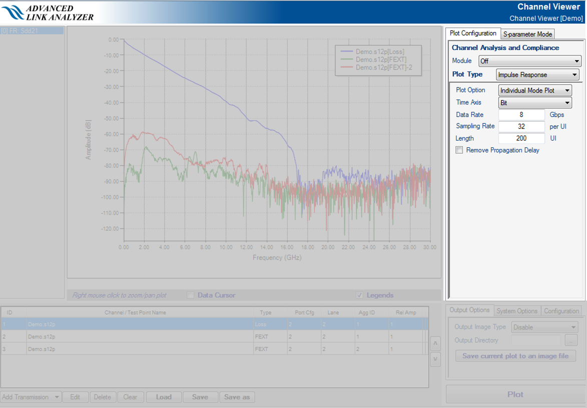
This panel allows you to select and configure the channel plotting. The Advanced Link Analyzer Channel Viewer can plot channel characteristics in either frequency domain or time domain. Typical frequency domain amplitude and group delay plots are shown in the following figure.
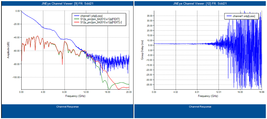
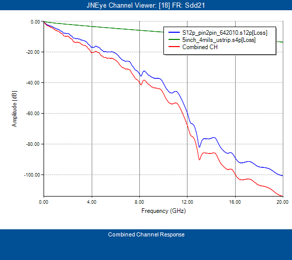
The Advanced Link Analyzer Channel Viewer plots the channels’ amplitude and group delay frequency responses in a linear or logarithmic frequency scale. It also allows you to limit the plot frequency range. When multiple transmission channels (such as loss or victim) are in the Channel List, you can plot the cascaded channel response by turning on the Plot Combined Channel Response option in the Systems Options panel. An example of a combined channel response is shown in the following figure, in which a lossy backplane channel is cascaded with a 5” microstrip PCB trace.
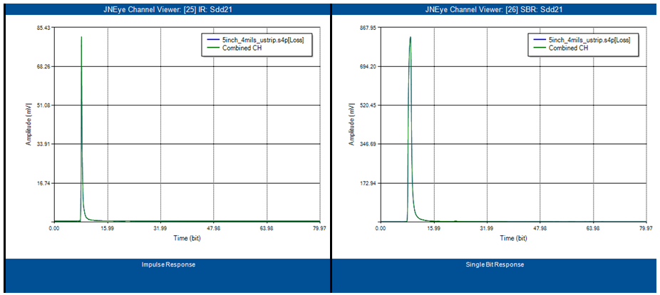
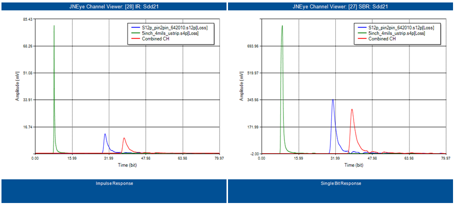
The Advanced Link Analyzer Channel Viewer can also plot channel responses in the time-domain. It can compute the impulse response (IR) and single-bit response (SBR) of a channel or a combined response of channels. When performing a time-domain plot, you must specify the maximum frequency and plot length of the time-domain response. The following figure shows examples of impulse response and single-bit response of a 5” microstrip PCB trace.
Combined time-domain channel responses can also be done in the Advanced Link Analyzer Channel Viewer. The following figure shows examples of combined time-domain channel response of a lossy backplane channel and a 5” microstrip PCB trace.
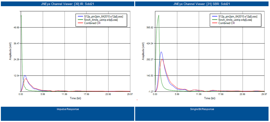
By turning on the Remove Propagation Delay option, the Advanced Link Analyzer Channel Viewer can mathematically remove the delay of channels so that more direct comparison among channels can be seen. The following figure shows an example of “Remove Propagation Delay” channel response of the same channels used in the previous figure.
Modulation Type – Select the modulation type that the channels operate and are checked against.
Channel Analysis
The following figure shows the Channel Analysis GUI.
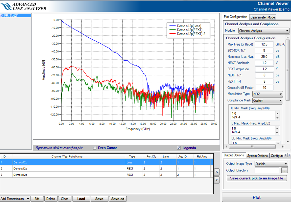
In the Channel Analysis Configuration panel, the following parameters can be configured to your link configuration or preferences:
- Max. Freq.—Maximum frequency where channel analysis is performed
- 20%-80% Tr/Tf—20%-80% rise/fall time of the input signal to the victim or transmission channel(s)
- Nom max IL at Nyquist—Nominal maximum insertion loss at Nyquist frequency. This parameter specifies the maximum allowed insertion loss at Nyquist frequency, which is defined as half of the maximum frequency specified above. This frequency is used to safe guard the correctness of the fitted insertion curves so that the results meet fundamental transmission line characteristics.
Note: Please enter the nominal maximal IL value which approximates to the selected channel at the Nyquist frequency. This value does not need to be precise as the fitting algorithm usually have enough tolerance margins in computing the fitted curves. If the channel's insertion loss at Nyquist frequency is less than 15dB, please enter 15 for best performance. If multiple channel are selected for the channel analysis, please enter the insertion loss value of the most lossy channel.
- NEXT Amplitude—Near-end crosstalk aggressor signal amplitude
- FEXT Amplitude—Far-end crosstalk aggressor signal amplitude
- NEXT Tr/Tf—Near-end crosstalk aggressor 20%-80% rise/fall time
- FEXT Tr/Tf—Far-end crosstalk aggressor 20%-80% rise/fall time
- Crosstalk dB Factor—This parameter, Y, defines how dB is calculated where dB = Y*log10(amplitude)
- Modulation Type—Select the modulation type that the channels operate and are checked against. The supported modulation types are NRZ (default) and PAM4.
- Compliance Mask—Select the channel compliance mask for channel analysis. The Compliance Mask menu contains the following selections:
- 10GBASE-KR—Use the 10GBASE-KR channel compliance mask.
- OIF CEI-28G-SR 3.0—Use the OIF CEI-28G-SR channel compliance mask.
- OIF CEI-25G-LR 3.0—Use the OIF CEI-25G-LR channel compliance mask.
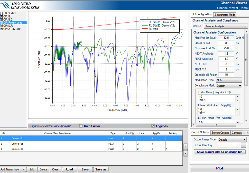
- Custom—Refer to Figure 143. Several text boxes for each channel compliance check item are shown. You can copy or manually input the mask definitions. The format for each mask definition data point is “Frequency (in Hz)", followed by "Amplitude (in dB)”. The number of data points is limited to the maximum text length allowed by the text box (the maximum size is 32767 bytes). The frequency grid of a mask must be monotonic increasing.
- Load from file—Allows you to load a predefined custom channel compliance. Each mask definition starts with a keyword, followed by a pair of numbers that represent the data points for “Frequency (Hz)" and "Amplitude (dB)”. Following is a sample of a custom channel compliance mask file:
IL Mask Min
1 0
1e9 -1
10e9 -2.5
IL Mask Max
1 0
1e9 1
10e9 2.5
ILD Mask Min
1 0
1e9 -4
10e9 -4
ILD Mask Max
1 0
1e9 4
10e9 4
RL Mask
1 -10
1e9 -10
10e9 -4
ICR Mask
1e9 55
25e9 25
ICN Mask
1 10
5 10
25 0
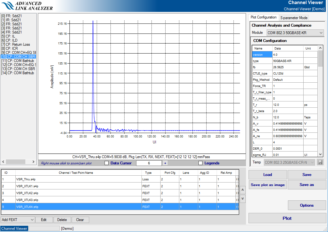
When you click Plot, the Channel Viewer computes and generates a sequence of plots that show the performance of the channels in the channel list
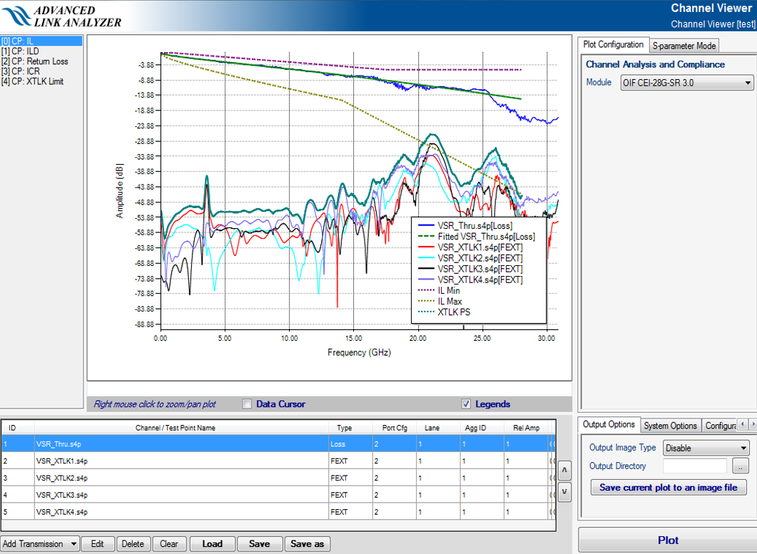
- Insertion Loss Plot—This plot is labeled CP: IL. In this plot, the insertion loss of channels, fitted curve of transmission channels’ insertion loss, crosstalk channels’ amplitude, and power sum of all crosstalk channels is shown. An example is illustrated in the above figure.
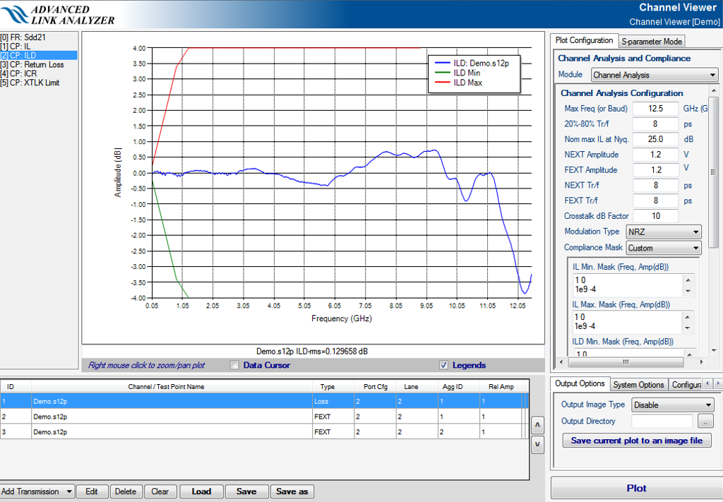
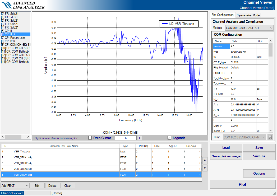
- Insertion Loss Deviation Plot—This plot is labeled CP: ILD. In this plot, the insertion loss deviation is shown, as in the following figure.
- Return Loss Plot—This plot is labeled CP: RL. In this plot, the return loss characteristics (both ends, i.e., Sdd11 and Sdd22) of channels are shown, as in the following figure.
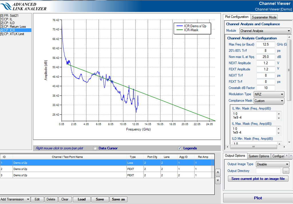
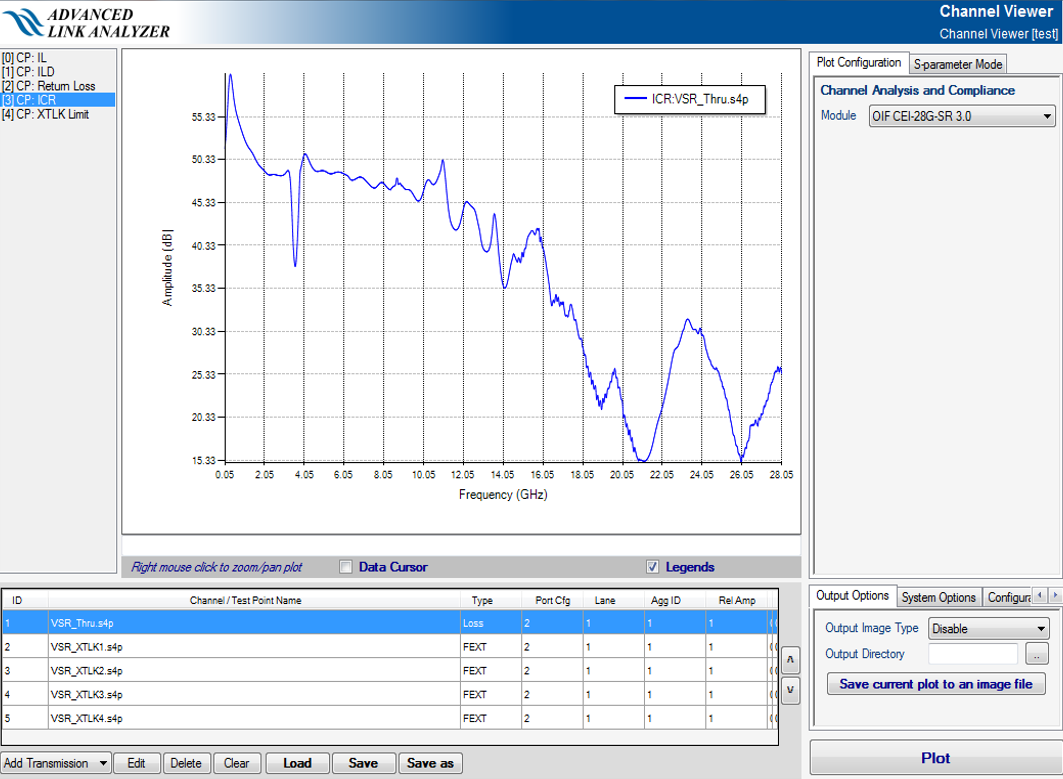
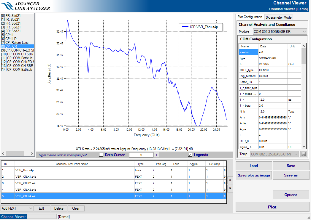
- Insertion Loss to Crosstalk Ratio Plot—This plot is labeled CP: ICR. In this plot, the Insertion Loss to Crosstalk Ratio (ICR) of channels is plotted. ICR is calculated as the distance between the insertion loss and combined crosstalk channels, as in the following figure. When the Crosstalk Limit plot is not enabled, the Channel Viewer also calculates and displays integrated crosstalk noise (ICN or XTLKrms) in mV-RMS units.
- Crosstalk Limit Plot—This plot is labeled CP: XTLK Limit. In this plot, a crosstalk noise figure, integrated crosstalk noise (ICN), or XTLKrms in mV-RMS units, is calculated based on your configurations, as in the following figure.

10GBASE-KR Channel Compliance
The following figure shows the 10GBASE-KR channel compliance check GUI.

All parameters are predefined as described in the IEEE 802.3ap/10GBASE-KR standards, so there is no user input. Click Plot to proceed. Channel Viewer computes and generates a sequence of plots that show the performance of the channels in the channel list.
- Insertion Loss Plot—This plot is labeled CP: IL. In this plot, the insertion loss of channels, fitted curve of transmission channels’ insertion loss, maximum insertion loss limits, crosstalk channels’ amplitude, and power sum of all crosstalk channels is shown. An example is illustrated in the above figure.
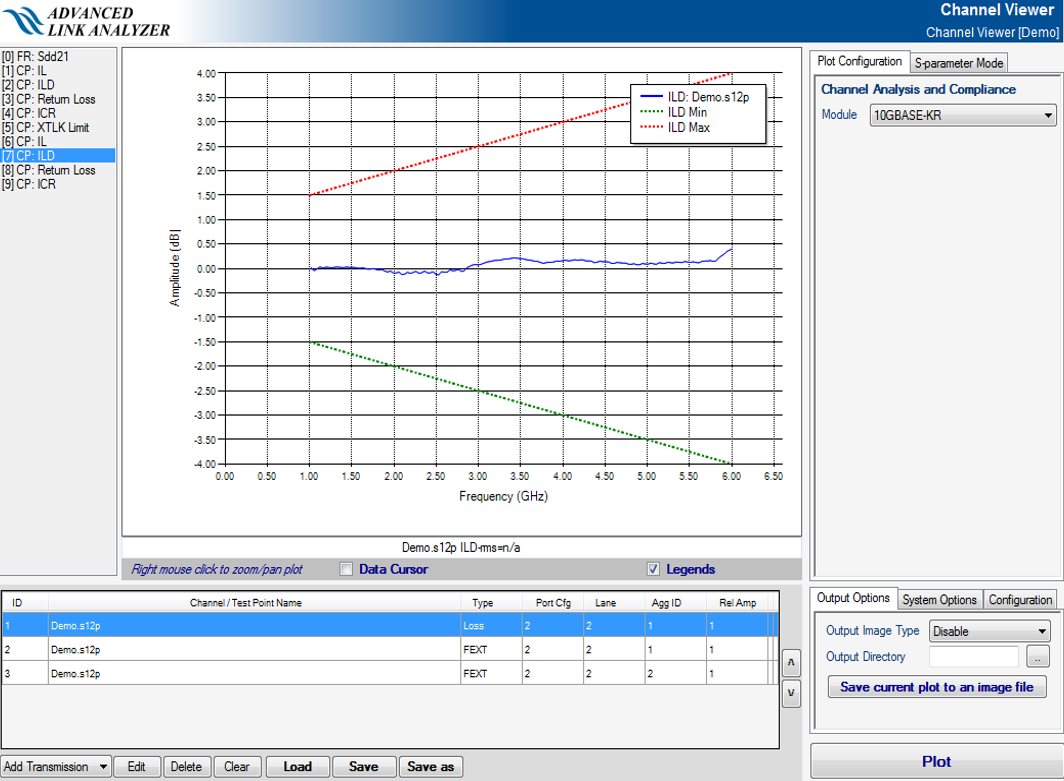
- Insertion Loss Deviation Plot—This plot is labeled CP: ILD. In this plot, the insertion loss deviation and ILD masks are shown, as in the following figure.
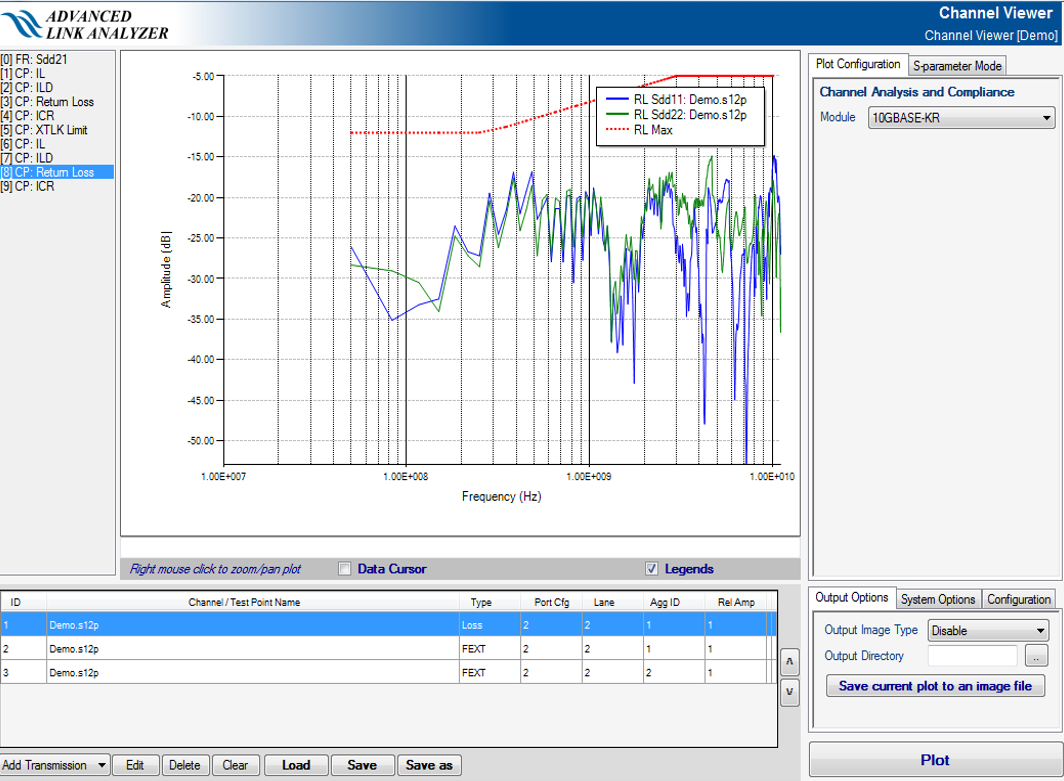
- Return Loss Plot—This plot is labeled CP: RL. In this plot, return loss (RL) characteristics of channels and the RL mask are shown, as in the following figure.
- Insertion Loss to Crosstalk Ratio Plot—This plot is labeled CP: ICR. In this plot, the Insertion Loss to Crosstalk Ratio (ICR) of channels and the ICR mask are plotted, as in the following figure.

OIF CEI-28G-SR 3.0 and OIF CEI-25G-LR Channel Compliances
The following figure shows the OIF CEI-28G-SR 3.0 channel compliance check GUI.
OIF CEI-25G-LR, OIF CEI-28G-MR, and OIF-CEI-28G-SR channel compliances are similar in configuration and usage. Both cases are covered in this section. All parameters are predefined as described in the OIF CEI-25G-LR, OIF CEI-28G-MR, and OIF-CEI-28G-SR standards, so there is no user input. Click Plot to proceed. Channel Viewer computes and generates a sequence of plots that show the performance of the channels in the channel list.
- Insertion Loss Plot—This plot is labeled CP: IL. In this plot, the insertion loss of channels, fitted curve of transmission channels’ insertion loss, insertion loss masks, crosstalk channels’ amplitude, and power sum of all crosstalk channels are shown. An example is illustrated in the above figure.
- Insertion Loss Deviation Plot—This plot is labeled CP: ILD. In this plot, the insertion loss deviation and ILD masks are shown, as in the following figure.

- Return Loss Plot—This plot is labeled CP: RL. In this plot, return loss (RL) characteristics of channels and RL mask are shown, as in the following figure.

- Insertion Loss to Crosstalk Ratio Plot—This plot is labeled CP: ICR. In this plot, the Insertion Loss to Crosstalk Ratio (ICR) of channels and the ICR mask are plotted, as in the following figure.
- Crosstalk Limit Plot—This plot is labeled CP: XTLK Limit. In this plot, a crosstalk noise figure, XTLKrms in mV at Nyquist frequency, is calculated based on your configurations, as in the following figure

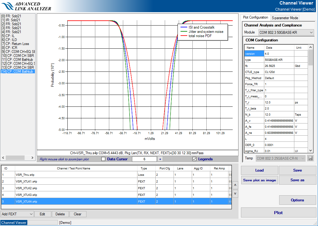
Channel Operating Margin (COM) Channel Compliance and Analysis
Advanced Link Analyzer Channel Viewer is equipped COM computation engine that can compute COM values for selected channels. Users can select and import channels, via Add Transmission/FEXT/NEXT pull down menu or click Channel Viewer button within Advanced Link Analyzer main GUI, select the intended standards or COM Analysis, and then followed by clicking the Plot button. Channel Viewer performs a sequence of computation and present the results.
- 100GBASE-CR4
- 100GBASE-KP4
- 100GBASE-KR4
- CAUI-4 C2C
- 200GAUI-4
- 400GAUI-8
- 200GAUI-4 C2M
- 400GAUI-8 C2M
- 200GBASE-CR4
- 100GBASE-CR2
- 50GBASE-CR
- 200GBASE-KR4
- 100GBASE-KR2
- 50GBASE-KR
- OIF-CEI-56G-LR
- OIF-CEI-56G-MR
- 100GBASE-KR1
- 200GBASE-KR2*
- 400GBASE-KR4*
- 100GBASE-CR1*
- 200GBASE-CR2**
- 400GBASE-CR4*
- 100GAUI-1 C2C*
- 200GAUI-2 C2C*
- 400GAUI-4 C2C*
- 100GBASE-C2M1* (for 100GAUI-1 C2M, 200GAUI-2 C2M, and 400GAUI-4 C2M)
- OIF-CEI-112G-LR*
- OIF-CEI-112G-MR*
- OIF-CEI-112G-VSR*
- JESD204C.1 Class R
- JESD204C.1 Class M
- JESD204C.1 Class S


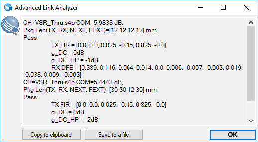
The COM result message box displays the COM analysis results and COM equalization settings. You can also copy the results to the clipboard by clicking Copy to clipboard or save the results to a text file by clicking Save to a file.
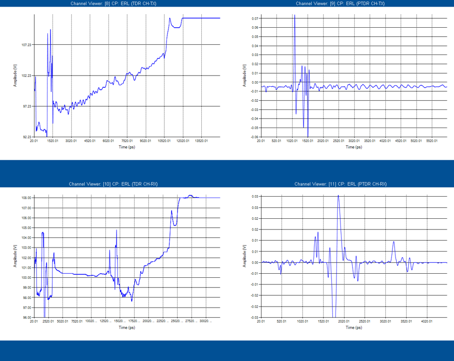
Effective Return Loss (ERL) Compliance and Analysis
Advanced Link Analyzer Channel Viewer is equipped with an ERL computation engine that can calculate ERL values for selected channel and device return loss data. You can select and import the channel's or device's return loss characteristics data file via the Add Transmission menu. To perform ERL analysis, use the Channel Analysis and Compliance Module menu, select the intended ERL analysis type, and then press Plot. The Channel Viewer performs a sequence of computations and presents the results.
- 50GBASE-KR: channel, transmitter, and receiver
- 100GBASE-KR2: channel, transmitter, and receiver
- 200GBASE-KR4: channel, transmitter, and receiver
- 50GBASE-CR: channel and receiver
- 100GBASE-CR2: channel and receiver
- 200GBASE-CR4: channel and receiver
- 100GBASE-KR1*: channel and device
- 200GBASE-KR2*: channel and device
- 400GBASE-KR4*: channel and device
- 100GBASE-CR1*: channel and device
- 200GBASE-CR2*: channel and device
- 400GBASE-CR4*: channel and device
- 100GAUI-1 C2C*: channel and device
- 200GAUI-2 C2C*: channel and device
- 400GAUI-4 C2C*: channel and device
- 100GBASE-C2M1* (for 100GAUI-1 C2M, 200GAUI-2 C2M, and 400GAUI-4 C2M): device (host and module)
- OIF-CEI-112G-LR*: channel and device
- OIF-CEI-112G-MR*: channel and device
- OIF-CEI-112G VSR*: device (host and module)

ERL computation engine that can calculate ERL values for selected channel and device return loss data. You can select and import the channel's or device's return loss characteristics data file via the Add Transmission menu. To perform ERL analysis, use the Channel Analysis and Compliance Module menu, select the intended ERL analysis type, and then press Plot. The Channel Viewer performs a sequence of computations and presents the results.
COM Analysis
The COM Analysis module allows you to perform customizable COM and ERL analysis. In the COM Analysis mode, the COM or ERL parameters can be edited.
You can use the Template (Temp in the GUI) menu below the COM parameter table to select a COM or ERL standard and use it as a starting point for customizations. You can also save and load customized COM parameters from the Template menu.
The original COM calculations assume certain scaling among the data rate (fb) and parameters, such as receiver continuous time linear equalizer’s (CTLE) pole and zero locations. When you want to compute COM at non-standard data rates or variable data rates (for OIF CEI standards for example), various COM parameters may need to be manually calculated and input into the table. The Channel Viewer’s COM analysis engine implements automatic scaling feature, for example, for receiver CTLE, TX rise/fall time, and so on, which allows the automatic frequency scaling of, for example, four CTLE parameters when CTLE_Auto_Scale is set to 1 in the COM configuration table. The CTLE scaling usage in the COM analysis is as follows:
- CTLE_f_p1_div_factor: f_p1 is equal to fb/CTLE_f_p1_div_factor
- CTLE_f_p2_div_factor: f_p2 is equal to fb/CTLE_f_p2_div_factor
- CTLE_fz_div_factor: fz is equal to fb/CTLE_fz_div_factor
- CTLE_f_HP_PZ_div_factor: f_HP_PZ is equal to fb/CTLE_f_HP_PZ_div_factor
CTLE scaling also covers CTLE with listed pole/zero sets (as in JESD204C.1).
You can enable the transmitter rise or fall time (T_r) automatic scaling factor by setting T_r_Auto_Scale to 1 and then specifying the scaling factor T_r_fb_custom_factor. The T_r is equal to 1/fb*T_r_fb_custom_factor. Similarly, you can configure the rise or fall time of TDR stimulus by setting TR_TDR_Auto_Scale to 1 and TR_TDR_fb_custom_factor where TR_TDR is 1/fb*TR_TDR_fb_custom_factor.
Advanced Link Analyzer’s COM computation engine has implemented the T_r_beta parameter associated with the Hr transfer function calculation as specified in IEEE 802.3 Annex 93A equation 93A-46. The Advance Link Analyzer applies the following equation:
T_r_beta value has been evolving since the COM methodology was first created and its value can be 1 or 2 depending on the clauses or the time standards at which the documents were revised/published. In the latest Ethernet and OIF-CEI clauses, T_r_beta is set to 2. You can override the template settings when running COM/ERL in COM Analysis mode when necessary.
COM Analysis Wizard can assist you setting up custom COM analysis configurations as illustrated in Figure 167.
In COM Analysis Wizard, you can specify custom link baud rate (fb), target BER rate (DER), CTLE scaling factors, and transmitter rise/fall time scaling factor. Channel Viewer then configures the COM (or ERL) parameters in the background before computing the COM or ERL.

ITOL Random Noise Calibration
Advanced Link Analyzer Channel Viewer is equipped with an ITOL (Interference Tolerance Test) Random Noise (RN) Calibration engine that computes the noise amplitude to stress the receiver-under-test (to COM threshold, commonly 3dB) per instructions/procedures from IEEE 802.3 standards. To use this feature, you start with selecting the COM RN Calibration entry under Channel Analysis and Compliance Module pull-down menu, and then select a COM compliance template (using Temp pull-down menu). The COM Random Noise Calibration Wizard shows how to guide the RN calibration configurations and analysis. Figure 168 shows the COM Random Noise Calibration Wizard GUI.
To perform RN calibration, two channel model files are required: Data Path S(tc), which represents the victim data path’s channel characteristics, and Noise Path S(nc), which represents the signal path connecting the noise source to the receiver-under-test, as illustrated in Figure 168. Inside the Channel Viewer, S(tc) is represented by the victim transmission path and S(nc) is represented by the first far-end crosstalk (FEXT) channel component, respectively. You can configure these two channels before initiating the COM RN Calibration Wizard or specify S(tc) and S(nc) within the Wizard.
There are five ITOL RN calibration parameters to be configured before conducting the calibration process. Note that specifying these parameters are optional which depends on your test bench, device, and/or instrument conditions. When custom parameters are not enabled or specified, the COM/ERL parameters from the COM table or template are used.
Apply Measured Jitter: when enabled (i.e. check the Apply Measured Jitter check box in the GUI), users can input PAM4 jitter values Jnu, where n is determined by the DER target for this RN calibration process, and Jrms in UI unit. Per IEEE 802.3 standards, the Jnu and Jrms are the measured TX jitter numbers. The wizard also shows the converted COM parameter A_DD and sigma_RJ for references.
Apply Measured SNDR: when enabled (i.e. check the Apply Measured TX SNDR check box), you can input the measured TX SNDR value per IEEE 802.3 specifications.
Apply Measured TX Rise/Fall Time (T_rm or T_r, only one can be applied): when enabled (i.e. either Apply Measured TX Rise/Fall Time (T_rm) or Apply Measured TX Rise/Fall Time (T_r) check box), you can input either T_rm or T_r in the associated text box with the unit of ps. While T_r is directly used in the COM process, T_rm is converted to T_r per IEEE 802.3 standards.
Exclude TX Package: when enabled (i.e. check the Exclude TX Package check box), TX package is excluded from the COM analysis. Per IEEE 802.3 specifications, TX package is excluded because RN calibration is usually performed using a signal or pattern generator.
Apply Custom RN Calibration Pass Threshold: when enabled (i.e. check the Apply Custom RN Calibration Pass Threshold check box), the RN calibration process uses the input value (in dB unit) as the stoppage criteria to terminate the RN calibration process. That is, if the threshold is 0.1dB, the RN calibration process stops when the resultant COM value is within the range between 2.9dB and 3.1dB assuming that the COM threshold is 3dB.
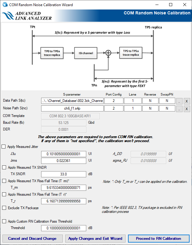
After configuring the RN calibration, you have three options:
Proceed to RN Calibration: start the RN calibration process. Upon completion of the calibration, a message box displays and reports the found RN value, i.e. sigma_bn in COM, and various COM results. Figure 169 illustrates an example of RN calibration output.

Apply Changes and Exit Wizard: clicking this button allows Channel Viewer to save your input to the COM/ERL table/template but without performing the RN calibration process.
Cancel and Discard Change: click this button to exit the wizard and all inputs are discarded.