A newer version of this document is available. Customers should click here to go to the newest version.
2.1.4.1. Jitter/Noise Setting
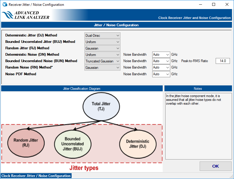
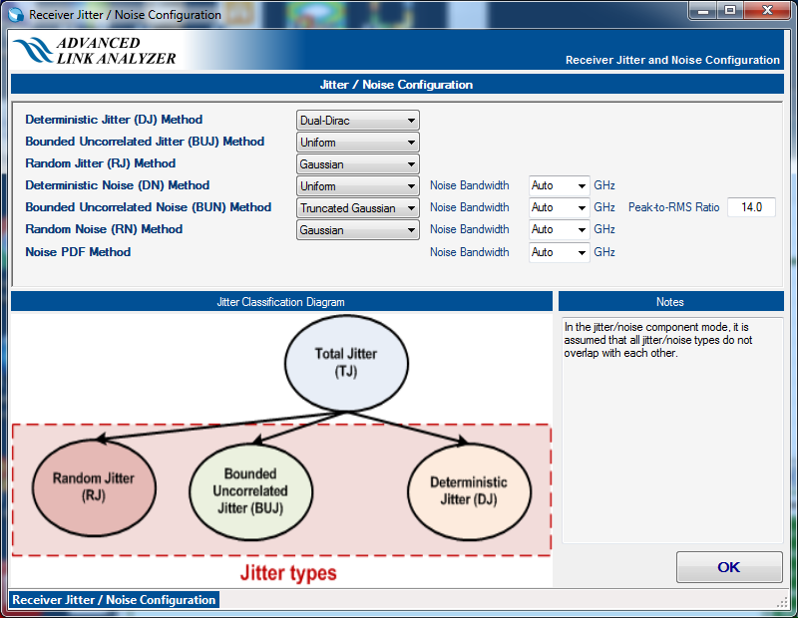
Advanced Link Analyzer provides extensive jitter and noise modeling and configuration capabilities. The receiver intrinsic jitter and noise types are categorized in the following table. You can configure each jitter and noise type by clicking Receiver Jitter Options, which leads to the Receiver Jitter/Noise Configuration window.
Advanced Link Analyzer uses a flat jitter/noise structure that assumes no overlapping among the jitter and noise components. Avoid double counting when inputting or importing jitter/noise figures. In the following figure, DJ contains DCD, ISI, PJ, and BUJ. This implies that when you specify DCD and BUJ, the DJ should not be used or the DJ figure should not contain any DCD and BUJ components.
| Name |
Description |
Unit |
Support in Advanced Link Analyzer |
Comments |
|---|---|---|---|---|
| DJ |
Deterministic Jitter |
UI |
Yes |
You can generate the receiver DJ by using a uniform distribution, dual-Dirac, or truncated Gaussian method. You can select the DJ generation method in the Receiver Jitter/Noise Configuration Window. The default receiver DJ method is dual-Dirac. |
| BUJ |
Bounded Uncorrelated Jitter |
UI |
Yes |
Same as receiver’s Deterministic Jitter. The default method is Uniform distribution. You can select the BUJ generation method in the Receiver Jitter/Noise Configuration Window. |
| RJ |
Random Jitter |
UI-RMS or ps-RMS |
Yes |
RJ is assumed to be Gaussian. You can specify the receiver RJ in eighth pico-second (ps-RMS) or unit-interval (UI-RMS). |
| DN |
Deterministic Noise |
mV |
Yes |
You can generate the receiver DN by using a uniform distribution, dual-Dirac, or truncated Gaussian method. You can select the DN generation method in the Receiver Jitter/Noise Configuration Window. The default DJ method is uniform. |
| BUN |
Bound Uncorrelated Noise |
mV |
Yes |
Same as receiver DN above. The default method is Truncated Gaussian method. You can select the BUN generation method in the Receiver Jitter/Noise Configuration Window. |
| RN |
Random Noise |
mV-RMS |
Yes |
RN is assumed to be Gaussian. |
| Jitter PDF |
Jitter Probability Density Function (PDF) |
Jitter amplitude, Probability (Jitter amplitude can be in absolute time or UI (unit interval) unit) |
Yes |
Jitter PDF defines the jitter probability density function. The input format is jitter amplitude in second and probability. The following is a jitter PDF example: -5e-12 1e-10 -4e-12 3e-7 -3e-12 1e-4 -2e-12 1e-2 -1e-12 0.29 0 0.4 1e-12 0.29 2e-12 1e-2 3e-12 1e-4 4e-12 3e-7 5e-12 1e-10 |
| Noise PDF |
Noise Probability Density Function |
Noise amplitude, Probability |
Yes |
Noise PDF defines the noise probability density function. The input format is Noise amplitude in volt and probability. The following is a noise PDF example: -50e-3 1e-10 -40e-3 3e-7 -30e-3 1e-4 -20e-3 1e-2 -10e-3 0.29 0 0.4 10e-3 0.29 20e-3 1e-2 30e-3 1e-4 40e-3 3e-7 50e-3 1e-10 |
| InpN |
Input Referred Noise |
V2/GHz | Yes (Except IBIS-AMI model and IBIS-AMI wrapper model) |
Receiver input referred noise is specified as one-sided noise spectral density in the unit of V2/GHz. It produces receiver-setting dependent noise figure for link margin calculation. |
Clock path receiver uses the same jitter/noise configuration method as the data path receiver.