A newer version of this document is available. Customers should click here to go to the newest version.
2.3.2. Channel List Panel
This panel maintains the channels of interest. Channels can be either transferred from the Advanced Link Analyzer Control Module or added within the Channel Viewer. The channel list in the Channel Viewer is independent from the list in Advanced Link Analyzer Control Module. Therefore, you can add and delete channels in the Channel Viewer without affecting the simulation configuration in the Advanced Link Analyzer Control Module.
An S-parameter channel component, such as a connector, cable, or backplane, can be described by the following parameters or information as shown in the Channel List:
- ID—Sequence or location of the channel component.
- Channel Name—An S-parameter file that describes the channel component. The S-parameter file can be 4-port, 8-port, 12-port, 16-port, and so forth.
- Type—Specify the type of channel characteristics in the link simulation. The type of channel characteristics can be insertion loss (Loss), far-end crosstalk (FEXT), or near-end crosstalk (NEXT). Change the channel type by selecting the channel from the channel list and then selecting the appropriate channel type from the Type menu.
- Port Configuration (Port Cfg)—Depending on the S-parameter measurement condition, the port configuration can be one of the types shown in the following figures. You can change the port configuration of an S-parameter by using the menu below the Port Configuration list box.
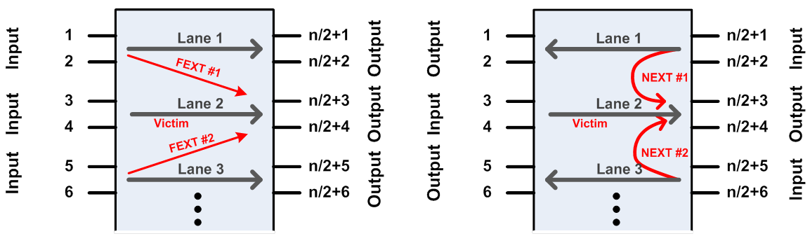
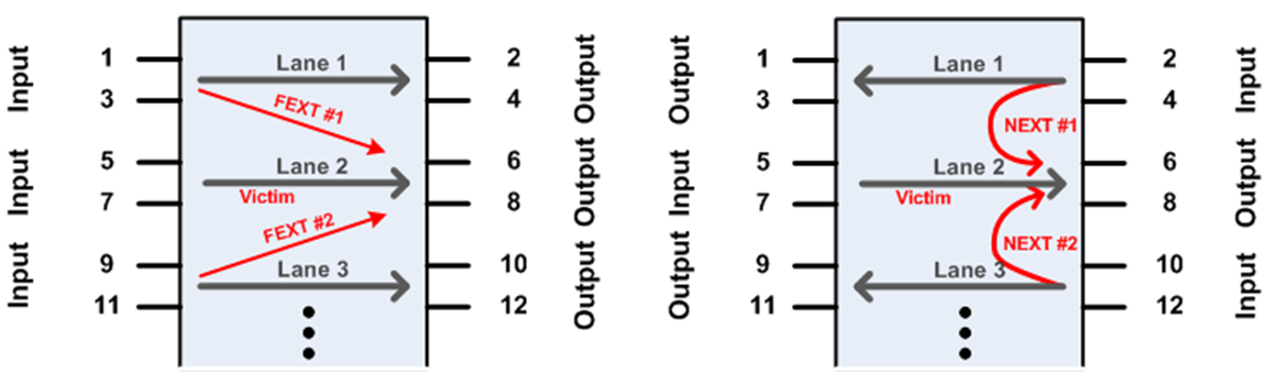
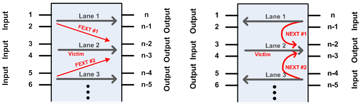
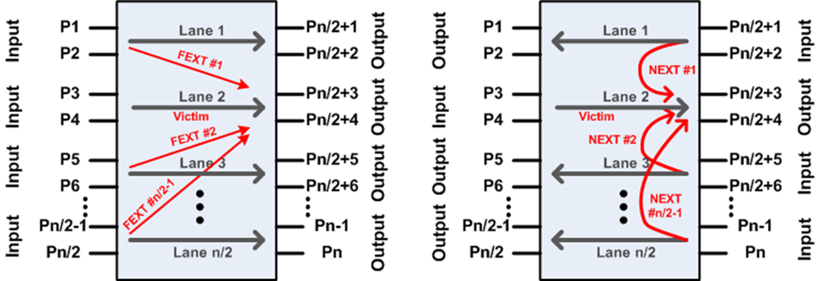
- Lane ID (Lane)—For multiple channel/lane S-parameters (8-port and above) a channel/lane must be chosen for link simulations. For example, the above figures show a 12-port 3-lane S-parameter. After loading the channel file, Advanced Link Analyzer assigns the middle lane as the default simulating channel (or victim channel for crosstalk simulations). You can change the Lane ID by using the menu below the Lane ID list box. For 2-port or 4-port S-parameter models, the Lane ID is ignored.
- Aggressor ID (Agg ID)—For multiple channel/lane S-parameters simulating crosstalk effects, you must specify the aggressor location. For example, the above figures show four possible crosstalk configurations from a 12-port S-parameter model. Use the menu below the Aggressor ID list box to change the aggressor location. For Victim channel (Loss type), the Aggressor ID field is ignored.
Note: The Aggressor ID is indexed in a way that excludes the victim lane. For example, in a 12-port S parameter, there are three lanes. The middle lane (Lane ID 2) is the victim lane. The two aggressor channels have Aggressor IDs 1 and 2, not 1 and 3.
- Relative Amplitude (Rel Amp)—You can manually adjust the amplitude of crosstalk (NEXT/FEXT) channel components. The amplitude adjustment is reflected in the channel plots and the channel compliance results. The amplitude adjustment is in a linear scale.
The Channel List Panel contains the following command buttons:
- Add Transmission/NEXT/FEXT/2-port Return Loss—Open a file browser and locate the specified channel model files.
- Edit—Open the Channel Wizard where you can change the selected channel or edit its properties, for example, port configuration, crosstalk aggressor, and so on.
- Delete—Delete the selected channel.
- Clear—Delete all channel components.
- Import Channel List—Import channels listed in a .csv file into the channel list for batch channel compliance tests. The .csv file must be in the following format:
- Each line specifies a channel file.
- Each channel file is specified with the following information separated by a comma (,):
- Full file name (include path)
- Channel type
- Port configuration
- Lane
- Crosstalk aggressor
- Crosstalk aggressor amplitude scale
- For compliance tests with crosstalk components, the list must start with the victim channel followed by the crosstalk components.
- For batch compliance tests with multiple groups of victim and crosstalk channel components, each group must start with the victim channel and end by either the end-of-list or a victim channel.
The following is an example of a channel list that contains three groups of victim and crosstalk channels:
D:\Ci_2\Cable_BKP_28dB_0p575m_more_isi_thru1.s4p,Loss,2,1,1,1 D:\Ci_2\Cable_BKP_28dB_0p575m_more_isi_f1.s4p,FEXT,2,1,1,1 D:\Ci_2\Cable_BKP_28dB_0p575m_more_isi_f2.s4p,FEXT,2,1,1,1 D:\Ci_2\Cable_BKP_28dB_0p575m_more_isi_f3.s4p,FEXT,2,1,1,1 D:\Ci_2\Cable_BKP_16dB_0p575m_more_isi_t.s4p,Loss,2,1,1,1 D:\Ci_2\Cable_BKP_16dB_0p575m_more_isi_f1.s4p,FEXT,2,1,1,1 D:\Ci_2\Cable_BKP_16dB_0p575m_more_isi_f2.s4p,FEXT,2,1,1,1 D:\Ci_2\Cable_BKP_16dB_0p575m_more_isi_f3.s4p,FEXT,2,1,1,1 D:\C2\CaBP_BGAVia_Opt2_28dB_THRU.s4p,Loss,2,1,1,1 D:\C2\CaBP_BGAVia_Opt2_28dB_FEXT2.s4p,FEXT,2,1,1,1 D:\C2\CaBP_BGAVia_Opt2_28dB_FEXT3.s4p,FEXT,2,1,1,1 D:\C2\CaBP_BGAVia_Opt2_28dB_FEXT4.s4p,FEXT,2,1,1,1 D:\C2\CaBP_BGAVia_Opt2_28dB_FEXT5.s4p,FEXT,2,1,1,1 D:\tg7_Thru_B56.s4p,Loss,2,1,1,1 D:\tg7_FEXT_B23.s4p,FEXT,2,1,1,1 D:\tg7_FEXT_B89.s4p,FEXT,2,1,1,1 D:\tg7_FEXT_C23.s4p,FEXT,2,1,1,1 D:\tg7_FEXT_C56.s4p,FEXT,2,1,1,1 D:\tg7_FEXT_C89.s4p,FEXT,2,1,1,1 - Export Channel List—Export the channels in the channel list to a .csv file.
- Move Up (/\)—Move the selected channel component or test point up toward the transmitter side.
- Move Down (\/)—Move the selected channel component or test point down toward the receiver side.