A newer version of this document is available. Customers should click here to go to the newest version.
2.1.3.1. Jitter/Noise Component
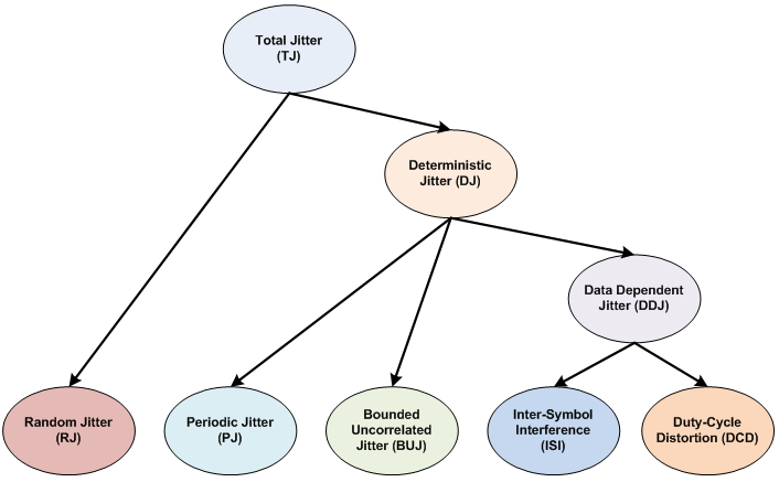
The following figure shows the jitter decomposition diagram and the breakdown of jitter components.
| Name |
Description |
Unit |
Support in Advanced Link Analyzer |
Comments |
|---|---|---|---|---|
| DJ |
Deterministic Jitter |
Unit Interval (UI) |
Yes |
DJ can be generated using a uniform distribution, dual-Dirac, or truncated Gaussian method. Select the DJ generation method in the Transmitter Jitter/Noise Options Window. The default DJ method is dual-Dirac. DJ consists of periodic jitter, bounded uncorrelated jitter, inter-symbol interference, and duty-cycle distortion. The DJ value is used in the simulation when the DJ/RJ-DN/RN method is selected. |
| ISI |
Inter-Symbol Interference |
UI |
Yes |
ISI can be generated using a uniform distribution, dual-Dirac, or truncated Gaussian method. Select the ISI generation method in the Transmitter Jitter/Noise Options Window. The default ISI method is dual-Dirac. |
| DCD |
Duty Cycle Distortion |
UI |
Yes |
The DCD parameter models two types of jitter: Positive pulse width jitter (PPWJ) and Clock DCD. The PPWJ shortens or lengthens the logic 1 waveform. The Clock DCD emulates distorted clock waveform effects on the transmitter output waveform. You can select the DCD generation method in the Transmitter Jitter/Noise Options Window. The default DCD method is PPWJ – (shortened positive waveform). |
| BUJ |
Bounded Uncorrelated Jitter |
UI |
Yes |
Same as Deterministic Jitter. The default BUJ method is Uniform distribution. |
| RJ |
Random Jitter |
UI-RMS or ps-RMS |
Yes |
RJ is assumed to be Gaussian. RJ can be specified in either pico-second (ps-RMS) or UI-RMS. |
| SJ |
Sinusoidal Jitter |
Amplitude: UI Frequency: MHz |
Yes |
Sinusoidal jitter can be specified with amplitude and frequency. |
| DN |
Deterministic Noise |
mV |
Yes |
DN can be generated using a uniform distribution, dual-Dirac, or truncated Gaussian method. You can select the DN generation method in the Transmitter Jitter/Noise Options Window. The default DN method is uniform. |
| BUN |
Bound Uncorrelated Noise |
mV |
Yes |
Same as DN. The default method is Truncated Gaussian method with a Peak-to-RMS ratio of 14. You can select the BUN generation method and parameters in the Transmitter Jitter/Noise Options Window. |
| RN |
Random Noise |
mV-RMS |
Yes |
RN is assumed to be Gaussian. |
| Jitter PDF |
Jitter Probability Density Function (PDF) |
Jitter amplitude, Probability (Jitter amplitude can be in absolute time or UI (unit interval) unit) |
Yes |
Jitter PDF defines the jitter probability density function. The input format is jitter amplitude in second and probability. The following is a jitter PDF example: -5e-12 1e-10 -4e-12 3e-7 -3e-12 1e-4 -2e-12 1e-2 -1e-12 0.29 0 0.4 1e-12 0.29 2e-12 1e-2 3e-12 1e-4 4e-12 3e-7 5e-12 1e-10 |
| Noise PDF |
Noise Probability Density Function |
Noise amplitude, Probability |
Yes |
Noise PDF defines the noise probability density function. The input format is Noise amplitude in volt and probability. The following is a noise PDF example: -50e-3 1e-10 -40e-3 3e-7 -30e-3 1e-4 -20e-3 1e-2 -10e-3 0.29 0 0.4 10e-3 0.29 20e-3 1e-2 30e-3 1e-4 40e-3 3e-7 50e-3 1e-10 |
| CMN |
Common Mode Noise |
mV-rms |
Yes |
It injects common noise into the link. User can specify the location of the noise injection either after the package or after the die. |
Click Jitter/Noise Options to further configure each jitter and noise type. There are two jitter/noise modes for Advanced Link Analyzer’s transmitters: Jitter/Noise Component mode and DJ/RJ-DN/RJ mode. Only one jitter/noise mode is active at a time and you must determine which mode to use in your simulations. Refer to Characterization Data Access for usage and meaning of Linked to Characterization Data check box in the Jitter/Noise panel.
- Jitter/Noise Component mode—Advanced Link Analyzer uses a flat jitter/noise structure that assumes no overlapping among all the jitter and noise components. Avoid double counting when inputting or importing jitter/noise figures. In the following figure, there are six specific jitter components: DCD, ISI, SJ, BUJ, RJ, and jitter PDF. The noise components DN, BUN, RN, and noise PDF must also be specified separately.
Figure 20. Specifying Transmitter Jitter and Noise in Jitter/Noise Mode
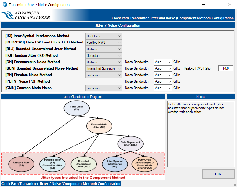
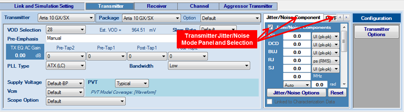 Figure 21. Transmitter Jitter/Noise Configuration in Jitter/Noise Component Mode
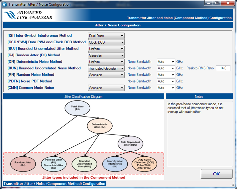
- DJ/RJ-DN/RJ mode—All deterministic jitter/noise components are included in DJ and DN.
Figure 22. Specifying Transmitter Jitter and Noise in DJ/RJ-DN/RJ Mode
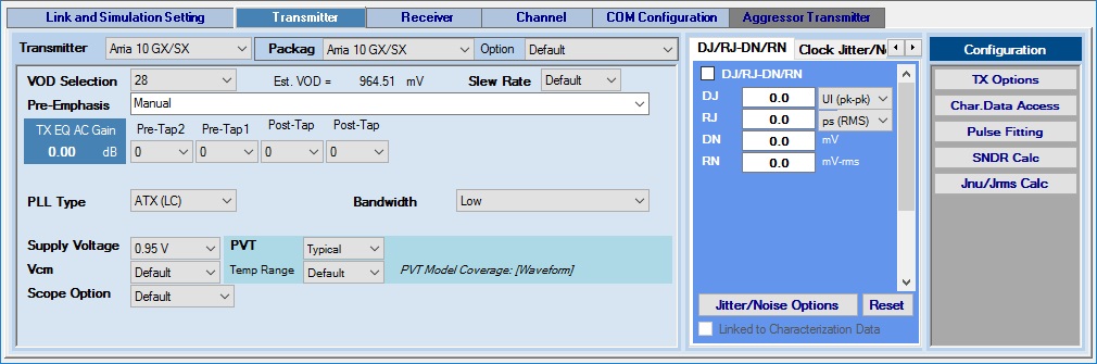 Figure 23. Transmitter Jitter/Noise Configuration in DJ/RJ-DN/RJ Method
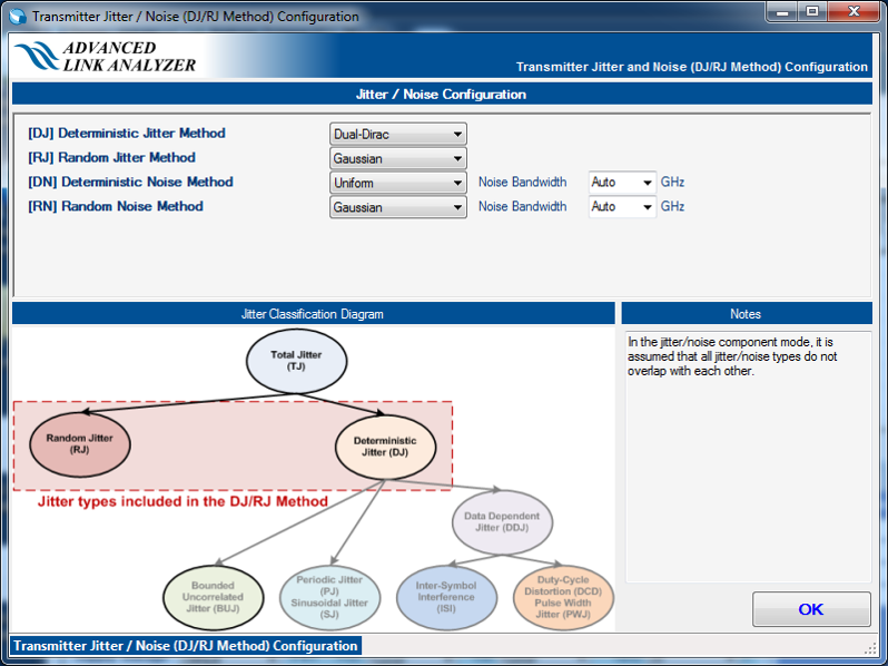
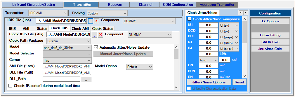
- Clock Jitter/Noise—Clock path transmitter uses the same jitter/noise configuration method as the data path transmitter’s jitter/noise component mode.
Figure 24. Specifying Clock Path Transmitter Jitter/Noise