2.1.3. Transmitter Setting
The transmitter generates signals based on the transmitter clock and test pattern conditions.
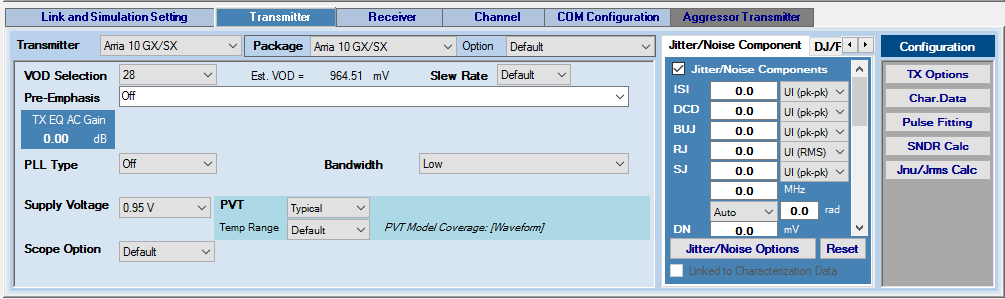
Transmitter
The following transmitter types are supported:
- Stratix® V GX
- Stratix® V GT
- Intel® Stratix® 10 L-tile
- Intel® Stratix® 10 H-tile
- Intel® Stratix® 10 E-tile (wrapper support)
- Intel® Stratix® 10 P-tile (wrapper support)
- Intel® Agilex™ E-tile (wrapper support)
- Intel® Agilex™ P-tile (wrapper support)
- Intel® Agilex™ R-tile (wrapper support)
- Intel® Agilex™ F-tile general-purpose transceiver block (wrapper support)
- Intel® Agilex™ F-tile high-speed transceiver block (wrapper support)
- Arria® V GZ
- Intel® Arria® 10 GX/SX
- Intel® Arria® 10 GT
- Intel® Cyclone® 10 GX
- IBIS-AMI
- Clock IBIS-AMI
- Custom
- PCI Express* 8 GT
- PCI Express* 16 GT
- PCI Express* 32 GT
The transmitter type determines what other transmitter settings you can select. When a transmitter is chosen, it is automatically inserted into the Link Designer, ready to connect to other link components.
Package
Select a package type for the transmitter device. For Intel products and IBIS-AMI models, the package models are included in the device models. For Custom devices, the package model is specified in the channel setting. When you select the Custom package type (for any transmitter devices), the embedded package model (if available) is disabled. You can then add a channel component (such as an S-parameter) with type Package in the Link Designer workspace. The Custom package model must be placed next to the transmitter module so it can be simulated and analyzed correctly. If you choose the Custom package type but do not add a channel component with Package type to the Link Designer workspace, the transmitter is simulated without any package model.
Selecting Package Designer from the Package pull-down menu opens the Transmitter Package Designer for you to design or customize package models.
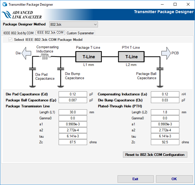
Advanced Link Analyzer’s Package Designer supports three package model generation methods. You can use the Package Designer Method pull-down menu to select one of following:
- IEEE 802.3 cd/bj COM: With this method, a package model is generated using the IEEE 802.3 50 Gbps Ethernet (802.3cd/bj is the task group name) Channel Operating Margin (COM) reference package modeling method. You can configure die capacitance, package material characteristics and length, and PCB bump. Refer to IEEE 802.3 Annex 92 for details. You can click either the Reset to 802.3cd COM Configuration button or Reset to 802.3bj COM Configuration button to reset all parameters to their default values per IEEE 802.3cd or IEEE 802.3bj, respectively.
- IEEE 802.3 ck COM: With this method, a package model is generated using the IEEE 802.3ck (task group for 100 Gbps Ethernet) COM reference package modeling method (shown in above figure). You can configure die capacitance, die termination network, die bump, package material characteristics and length, package vertical transition (for example, via) material characteristics and length, and PCB bump. Refer to IEEE 802.3 Annex 92 and 802.3ck for details. You can click the Reset to 802.3ck COM Configuration button to reset all parameters to their default values per IEEE 802.3ck.
Custom S-parameter: With this method, you can specify an S-parameter to represent the package model.
Advanced Link Analyzer comes with the following transmitter package models:
- Stratix® V GX
- Stratix® V GT
- Arria® V GZ
-
Arria 10 GX/SX
Options: Additional package models (shown in the following figure) are available for Intel® Arria® 10 devices. The package model is specified as its trace length inside the package. These models are chosen to cover the range of package trace lengths in Intel® Arria® 10 transceiver transmitters.
- Default—The default package model is the same as the 14 mm option
- 14mm
- 16.5mm
- 20mm
- 24mm
Contact My Intel support representative if you want to know how to pair your design with the Intel® Arria® 10 package model options.
Figure 17. Intel® Arria® 10 Transmitter Package Options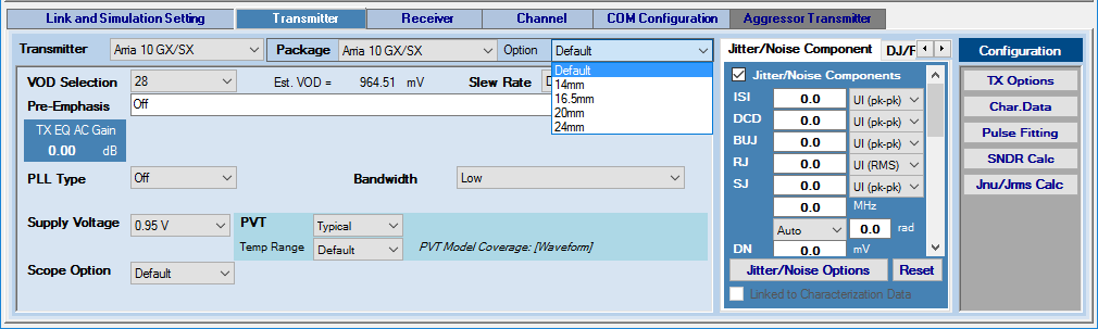
- Intel® Stratix® 10 L-tile—Typical, Minimum, and Maximum package models are provided
- Intel® Agilex™ R-tile/F-tile—Typical, Minimum and Maximum package models are provided
- Intel® Arria® 10 GT—Same options as Intel® Arria® 10 GX/SX
- PCI Express* 8 GT
- PCI Express* 16 GT (place holder only; use custom package model for simulations)
- PCI Express* 32 GT
- Intel® Stratix® 10 H-tile— Same options as Intel® Stratix® 10 L-tile
- Intel® Stratix® 10 E-tile— Same options as Intel® Stratix® 10 L-tile
- Intel® Cyclone® 10 GX—Typical, Minimum, and Maximum package models are provided
VOD Selection
Select the VOD (differential output voltage) for the transmitter. VOD selections can be either by voltage level or by index, depending on the transmitter selected. For supported devices, the target VOD value is displayed in the Transmitter tab page. The VOD value depends on the device type, supply voltage, and PVT.
Slew Rate
Select the transmitter output signal slew rate. Slew rate options are available for selected devices. For details, refer to the associated transceiver user guides.
Pre-Emphasis
Select or specify the transmitter pre-emphasis, de-emphasis, or TX-FIR configuration in one of the following modes:
- Auto—Advanced Link Analyzer uses its link optimization algorithm to find the optimal transmitter FIR settings.
- Auto with Manual Starting Point—Specify the initial TX pre-emphasis or FIR configuration. Advanced Link Analyzer’s link optimization engine uses the TX settings as initial conditions.
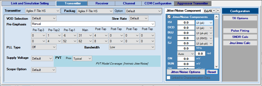
- Manual—For non-Intel devices, you can manually input the tap coefficients. For Intel devices, select individual FIR levels from the menus for each FIR tap. The FIR selection for Intel devices is VOD dependent. Therefore, changing the VOD or device type can reset the TX FIR menu contents. For a generic transmitter type, a set of typical FIR coefficients is included in the pull-down menu.
- Off
When you select the Intel® Agilex™ F-tile high-speed transceiver with wrapper support enabled, the transmitter GUI is capable of translating between high-speed transmitter’s FIR settings and register settings, which are used in the Intel® Quartus® Prime software.
Estimated TX EQ AC Gain
Select pre-tap and post-tap values to estimate the AC gain in dB scale. The TX EQ AC gain is calculated as the gain between the DC (0 Hz) and the Nyquist frequency of the link. This gain assumes a FIR type of transmitter pre-emphasis scheme and an ideal transmitter output waveform.
PLL Type and Bandwidth
Select the type and bandwidth of the PLL used in the transmitter to generate the transmitter clock.
- Ideal Clock—The default PLL setting. The PLL is disabled and the clock is passed from the external reference clock.
- For Intel transmitters, PLL models and configurations are automatically set based on the following settings:
- Data rate
- Reference clock frequency
- Oscillator type:
- Stratix® V GX and Arria® V GZ—ATX (LC) or CMU
- Stratix® V GT—ATX (LC)
- Intel® Arria® 10 GX/SX/GT—ATX (LC), Fractional PLL, or CMU
- Intel® Stratix® 10 L-tile/H-tile/E-tile—ATX (LC), Fractional PLL, or CMU
- Intel® Cyclone® 10 GX— ATX (LC), Fractional PLL, or CMU
- Intel® Agilex™ —TX PLL
- PLL bandwidth
- Intel transmitter PLL configurations such as internal divider ratios
Intel recommends that you follow Intel’s reference clock selection and PLL configurations recommendations when setting up the transmitter PLL. Without following the reference clock and PLL guidelines, you might operate and simulate an unstable PLL and see unexpected results.
- For Custom transmitters, PLL models and configuration are set automatically based on settings similar to that of Intel PLLs while more comprehensive PLL configuration capabilities are under development. With custom transmitters, the VCO can be either LC type or ring oscillator (Ring) type. More PLL to reference clock divider ratios are supported in the custom PLL type. Follow Intel's PLL and reference clock guidelines when setting up transmitter PLLs to avoid unexpected results.
- PLL is currently not supported for native IBIS-AMI transmitters.
Supply Voltage
For supported devices, you can choose the supply voltage.
- 0.95 V ( Intel® Arria® 10 GX/SX/GT)
- 1.03 V ( Intel® Arria® 10 GX/SX/GT)
- 1.12 V ( Intel® Arria® 10 GT)
- 1.03 V
- 1.12 V
- 1.03 V
- 1.12 V
- 0.95 V
- 1.03 V
Vcm
Vcm is the common voltage of the transmitted signal.
Scope Option
Advanced Link Analyzer has four options for TX output scope emulation:
- Default
- BW = Data Rate / 1667 (default value)
- BW = 4 MHz
- Disable
PVT
Select the process, voltage, and temperature (PVT) models for the selected transmitter device. PVT model support varies depending on device type, device data availability, and model coverage. A message is shown on the Transmitter tab page to indicate the PVT model coverage. Transmitter PVT model coverage and conditions are shown in the following table.
| Transmitter Type | Waveform PVT Model | Jitter/Noise PVT Model |
|---|---|---|
| Stratix® V GX | Typical | Process: Typical/Fast/Slow Voltage: Typical/High/Low Temperature: –40°C to 100°C |
| Arria® V GZ | Typical | Process: Typical/Fast/Slow Voltage: Typical/High/Low Temperature: –40°C to 100°C |
| Stratix® V GT | Typical | Process: Typical/Fast/Slow Voltage: Typical/High/Low Temperature: 0°C to 100°C |
| Intel® Arria® 10 GX/SX | Typical/Fast/Slow | Slow |
| Intel® Arria® 10 GT | Typical/Fast/Slow | Slow |
| Intel® Stratix® 10 L-tile | Typical/Fast/Slow | Slow |
| Intel® Stratix® 10 H-tile | Typical/Fast/Slow | Slow |
| Intel® Cyclone® 10 GX | Typical/Fast/Slow | Slow |
| Wrapper-supported Intel IBIS-AMI Models | Provide by IBIS-AMI model | Provide by IBIS-AMI model |
| IBIS-AMI | Provide by IBIS-AMI model | Provide by IBIS-AMI model |
| Custom | None | None |
| PCI Express* 8GT | None | None |
| PCI Express* 16GT | None | None |
Temp Range
For Intel® Arria® 10, the device model have temperature range dependency. The temperature range for Industrial is -40 °C to 100 °C, 0 °C tp 105 °C for Extended, and -40 °C to 125 °C for Military. The default setting is Industrial temperature range. Refer to the device's data sheet for the supported temperature range; values in the datasheet take precedence over the values in this document.
Advanced Link Analyzer to Intel® Quartus® Prime Parameter Translation for Intel® Arria® 10 GX/SX/GT Transmitters
The following table provides a translation from Advanced Link Analyzer Intel® Arria® 10 GX/SX/GT transmitter parameter names to the equivalent Intel® Quartus® Prime parameter names. Use the Intel® Quartus® Prime software to transfer optimum device settings from a Advanced Link Analyzer simulation to an actual device configuration.
| Advanced Link Analyzer Name | Intel® Quartus® Prime Name |
|---|---|
| Vod Selection | Transmitter Output Swing Level |
| Post-Tap 1 1 | Transmitter Pre-Emphasis First Post-Tap Magnitude |
| Post-Tap 2 1 | Transmitter Pre-Emphasis Second Post-Tap Magnitude |
| Pre-Tap 1 1 | Transmitter Pre-Emphasis First Pre-Tap Magnitude |
| Pre-Tap 2 1 | Transmitter Pre-Emphasis Second Pre-Tap Magnitude |
| Sign of Post-Tap 1 1 | Transmitter Pre-Emphasis First Post-Tap Polarity 2 |
| Sign of Post-Tap 2 1 | Transmitter Pre-Emphasis Second Post-Tap Polarity 2 |
| Sign of Pre-Tap 1 1 | Transmitter Pre-Emphasis First Pre-Tap Polarity 2 |
| Sign of Pre-Tap 2 1 | Transmitter Pre-Emphasis Second Pre-Tap Polarity 2 |
PLL Type
|
Intel® Quartus® Prime PLL Type
|
| Slew Rate | XCVR_A10_TX_SLEW_RATE_CTRL |
| PLL Bandwidth | Bandwidth in PLL Configuration Options in selected PLL type |