Answers to Top FAQs
1. Overview of the Power and Thermal Calculator
2. Estimating Power Consumption with the Power and Thermal Calculator
3. Power and Thermal Calculator Graphical User Interface
4. Power and Thermal Calculator Pages
5. Factors Affecting the Accuracy of the PTC
6. Power and Thermal Calculator User Guide Archive
7. Document Revision History for the Power and Thermal Calculator User Guide
A. Measuring Static Power
4.1. PTC - Power Summary/Navigation
4.2. PTC - Common Page Elements
4.3. PTC - Main Page
4.4. PTC - Logic Page
4.5. PTC - RAM Page
4.6. PTC - DSP Page
4.7. PTC - Clock Page
4.8. PTC - PLL Page
4.9. PTC - I/O Page
4.10. PTC - Transceiver Page
4.11. PTC - HPS Page
4.12. PTC - Crypto Page
4.13. PTC - NOC Page
4.14. PTC - HBM Page
4.15. PTC - Thermal Page
4.16. PTC - Report Page
4.13. PTC - NOC Page
The NOC page of the Power and Thermal Calculator (PTC) shows the power information relating to the network-on-chip IP.
To enable parameter entry into the NOC page, first select a device that supports NOC on the Main page or in Device Selection.
Note: Not all Agilex™ 7 devices have the NOC IP. Parameter entry is unavailable if the currently selected device does not have the NOC IP.
Figure 51. NOC Page of the PTC
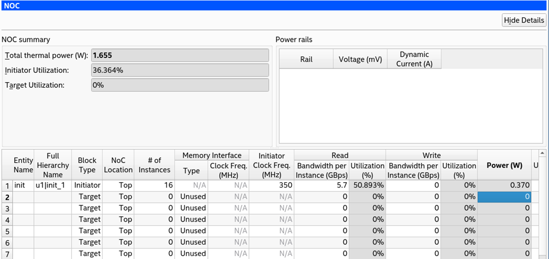
| Column Heading | Description | |
|---|---|---|
| Entity Name | Specify a name for each entity of the design. This is an optional entry. | |
| Full Hierarchy Name | Specify the hierarchical path relevant to this entry. This is an optional entry. When entering levels of hierarchy, the pipe character (|) denotes a level of hierarchy. | |
| Block Type | Specify whether the block is of type Target or Initiator. | |
| NoC Location | Specify whether the block is located at the Top or Bottom of the device. | |
| # of Instances | Specify the number of instances of this element. A single NoC Initiator Intel FPGA IP may contain multiple initiator interfaces. Similarly, a target memory IP such as the High Bandwidth Memory (HBM2E) Interface FPGA IP may contain multiple target interfaces. This page only reflects the power usage of the NoC targets of IP such as the High Bandwidth Memory (HMB2E) Interface FPGA IP. Estimate the power for the remainder of this IP elsewhere within PTC, for example on the HBM page. | |
| Memory Interface | Type | For target elements only. In the Type column, select between HBM for HBM2e memory or DDR for external memory interfaces implemented in GPIO-B blocks. In the Clock Freq. (MHz) column, enter the clock frequency for these target interfaces |
| Clock Freq. (MHz) | ||
| Initiator Clock Freq. (MHz) | For initiator elements only, enter the clock frequency the user interface for these initiators will operate at. If different initiators operate at different frequencies, they will need to be specified on separate rows. | |
| Read | Bandwidth per Instance (GBps) | For both initiator and target elements. Specify read and write bandwidth in the Bandwidth per Instance (GBps). Initiator or target elements with different bandwidth requirements need to be specified on separate rows. The Utilization (%) displays the bandwidth utilization for each initiator or target. A warning is generated if the read bandwidth utilization and write bandwidth utilization add up to more than 100%. |
| Utilization (%) | ||
| Write | Bandwidth per Instance (GBps) | |
| Utilization (%) | ||
| Power (W) | Reports the power for the total initiators or targets specified on that row. | |
| User Comments | Enter any comments. This is an optional entry. | |
Related Information