3.2.2.2. Entering Hierarchy Information Into the PTC
When entering levels of hierarchy in the PTC, the pipe character (|) denotes a level of hierarchy. For example, the following notation indicates three levels of hierarchy. Hierarchy a is the highest level. Hierarchy b is the second level. Hierarchy c is the third level.
a|b|c
Instance paths may, optionally, begin with a leading pipe character (|). But regardless of whether a leading pipe is is there or not, paths are treated the same.
When you enter an entity name for a given hierarchy, the PTC automatically updates the entity name in the Design Hierarchy tab of the Hierarchy Manager and on all data-entry pages that include that hierarchy.
To enter design hierarchy information into the PTC, follow these steps:
- Open your version of the PTC, as Accessing the Power and Thermal Calculators describes.
- Click the View menu and select one of the PTC pages, such as the Logic page.
Figure 16. PTC Logic Page
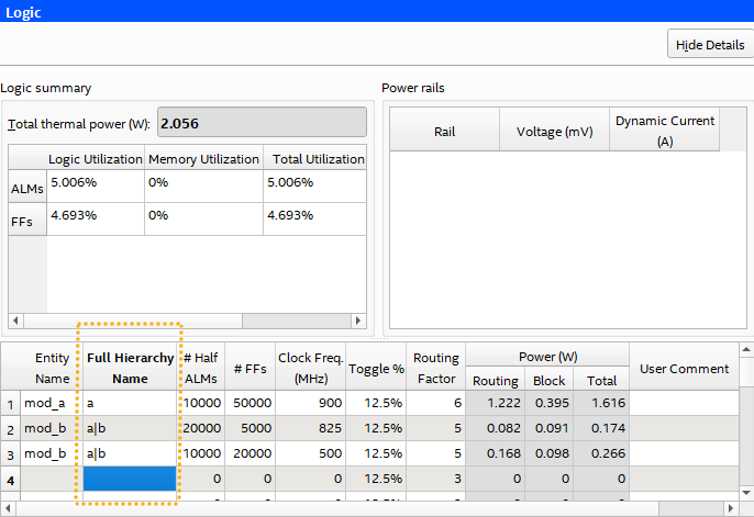
- In the Full Hierarchy Name cell, type the hierarchical name of a hierarchy in your design, using the pipe character (|) as the hierarchy level delimiter. For example, the following defines the b level of hierarchy that is child of hierarchy a:
a|b
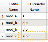
Figure 17. Entering Full Hierarchy Name in Intel® FPGA PTC
- In the Entity Name cell, enter the name of the design entity. If a newly entered hierarchy name already exists in the design, the Entity Name cell is already populated. Also, changing the entity name for a particular hierarchy name changes it for all_occurrences of that hierarchy name.
- Specify values for the #Half ALMs, #FFs, Clock Freq. (MHz), Toggle % and Routing Factor cells for each hierarchy. Repeat appropriate entries for design hierarchies on other pages.
The instance appears hierarchically in the Design Hierarchy in the PTC, showing the dynamic power estimate for each hierarchy level, and the cumulative power for all instances and hierarchy levels.
Figure 18. PTC Design Hierarchy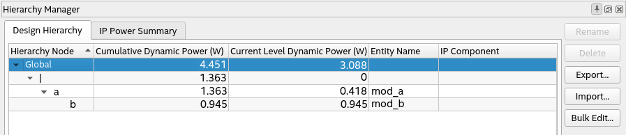
- In the Design Hierarchy, you can right-click any instance to Rename, Duplicate, or Export the PTC data for the levels of hierarchy that you define.