5.1.2.1. Simulation Results
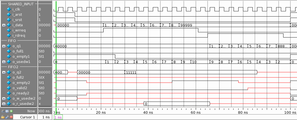
Part 1 (0 - 100 ns)

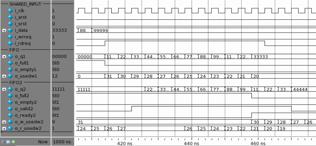
Part 2 (100 - 480 ns)


- usedw signal: After the write request signal (e.g., i_wrreq) is asserted, the usedw signal of FIFO (e.g., o_usedw1) starts counting as data is being stored into FIFO. For FIFO2, it has usedw signal on both write (e.g., o_w_usedw2) and read (o_r_usedw2) sides. The write usedw starts counting after 3 cycles of delay, and it takes another 8 cycles to update the read usedw signal.
- Full and empty signals: The FIFO full signal (e.g., o_full1) asserts high after the memory of FIFO is full. The FIFO2 full signal (e.g., o_full2) is asserted high on the same cycle as the o_w_usedw2 signal, which indicates that the memory is full. Note that when the three cycles before the full signal is asserted, the ready signal is already asserted low, which is an expected pipeline behavior of FIFO2. The FIFO empty signal (e.g., o_empty1), which has only one clock cycle of latency, asserts low after the first data is being written into memory. In contrast, FIFO2 takes three cycles of delay to indicate that its empty signal (e.g., o_empty2) has turned not-empty, after the o_r_usedw2 signal is risen to 1.

- On the read operation, the FIFO o_usedw1 signal is reflected on same positive clock edge with the read request signal. For FIFO2, two cycles of latency is observed before it is reflected on the o_r_usedw2 signal. It also takes another 9 cycles of propagation from o_r_usedw2 to o_w_usedw2.

- Ready signal: After a valid reset scheme, the FIFO2 ready signal (e.g., o_ready2) asserts high, which indicates that it is ready for the write operation.
Note: FIFO does not have this signal.
- Valid signal: The FIFO2 valid signal (e.g., o_valid2) is to indicate that the data being read out is valid. In the case of a valid read operation, the o_valid2 signal will assert high after two cycles of delay, with the assertion of the read request (e.g., i_rdreq) signal.
Note: FIFO does not have this signal.
Part 3 (480 - 700 ns)
This section of the simulation showcases a valid reset condition, followed by a read-during-write operation. After reset, the write request signal (e.g., i_wrreq) asserts high. After a few cycles later, the i_rdreq signal also asserts high. For FIFO, the number of used word maintains while the data is being read out, which follows an expected behavior. Note that in this case, FIFO2 has no data being read out because the o_empty2 signal is not asserted low. Therefore, it is not a valid read operation for FIFO2.
Part 4 (700 ns and onwards)
This section of the simulation observes the behaviour of FIFO and FIFO2 under different scenario. When the FIFO2 o_r_usedw2 signal counts down to 2, the o_empty2 signal asserts high and undergoes an internal check. After two cycles, the o_empty2 signal goes back to a not-empty state after the status is validated. This mechanism is specially designed for FIFO2 according to its multiple pipeline nature.