1.5. CFP2 Interface Optimization
The CFP2 host connector layout optimization reduces the impact of discontinuity at the differential pair to the CFP2 connector interface. A reference plane cutout is provided beneath the connector pads and larger oval anti-pads are used for the signal vias. Four nearby ground return vias are provided to help reduce the connector interface discontinuity.
Figure 10. CFP2 Connector Interface Layout Optimization
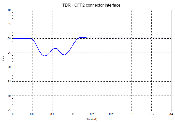
Figure 11. HFSS Simulated TDR of the CFP2 Connector interface The following figure shows the HFSS simulated TDR results. With the layout optimizations, the TDR deviation due to the discontinuity caused by the via and connector pad is kept within ±10% of the nominal 100Ω target impedance.