1.2. CFP2 Host Connector Assembly and Pinout
The CFP2 specification defines the mechanical connector requirements for the 104-pin CFP2 connector. The host connector assembly is composed of a female host connector, and a metal connector cover and cage for retention and electromagnetic shielding of the inserted CFP2 optical module.
Figure 3. CFP2 Host Connector Assembly for a 4x25G/28G Module Interface as Defined by the CFP2 Mechanical Specification
Note: This figure is courtesy of Yamaichi Electronics.
Figure 4. CFP2 Host Connector Pinout for 4x25G/28G Module Interface as Defined by the CFP2 Mechanical Specification
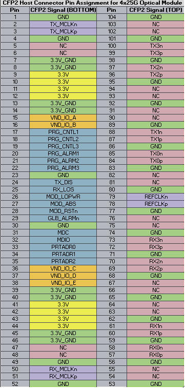
Figure 5. CFP2 Host Connector Layout Footprint The high-speed transceiver pins are identified in the following figure to show their position within the connector. Blue pins are the TX transceiver channels and red pins are the RX transceiver channels.