A newer version of this document is available. Customers should click here to go to the newest version.
4.2. FIR Decimation Filters
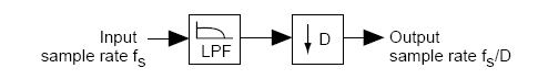
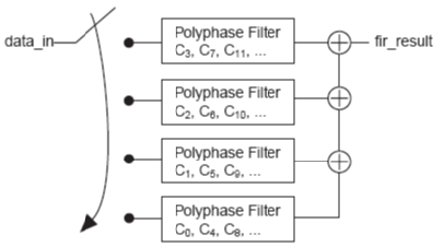
The FIR II IP core implements decimation filters using a single engine that is time-shared by the different phases to optimize area. This implementation changes the overall throughput of the filter and the input sample rate. The throughput of the filter is the rate at which the filter generates the output (one output every K clock cycles). The input sample rate is the rate at which the filter processes input data samples (the input needs to be held for L clock cycles).
The values of K and L for the throughput and input sample rate of FIR II decimation filters depend on the filter architecture.
| Architecture | Equations |
|---|---|
| Fully serial | K = ND L = N |
| Multibit serial | K = ND/M L = N / M |
| Fully parallel | K = D L = 1 |
| Multicycle | K = CD L = C |
For systems that require higher throughput and input data rate, Intel recommends that you use parallel or multicycle variable structures.