P-Tile Avalon® Streaming Intel® FPGA IP for PCI Express* User Guide
A newer version of this document is available. Customers should click here to go to the newest version.
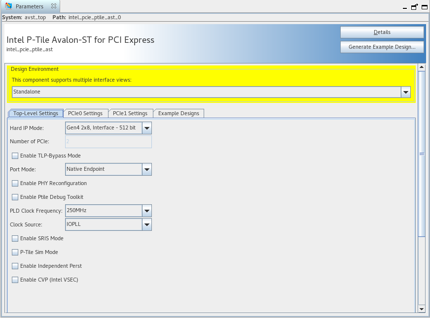
5.1. Top-Level Settings
| Parameter | Value | Default Value | Description |
|---|---|---|---|
| Hard IP Mode | Gen4x16, Interface - 512-bit Gen3x16, Interface - 512-bit Gen3x16, Interface - 256-bit Gen4 2x8, Interface - 512-bit Gen4 2x8, Interface - 256-bit Gen4 1x8, Interface - 256-bit Gen3 2x8, Interface - 256-bit Gen3 1x8, Interface - 256-bit Gen4x4, Interface - 128-bit Gen3x4, Interface - 128-bit |
Gen4x16, Interface - 512-bit |
Select the following elements:
Lane data rate:
Lane width:
|
| Number of PCIe | Total number of cores. This parameter is set by the choice made for Hard IP Mode. | ||
| Port Mode | Root Port Native Endpoint
Note: These are the available options when Enable TLP Bypass is set to False. If TLP Bypass mode is enabled, refer to the table Port Mode Options in TLP Bypass below for available port mode options.
|
Native Endpoint |
Specifies the port type. |
| Enable PHY Reconfiguration | True/False | False | Enable the PHY Reconfiguration Interface. |
| Enable Ptile Debug Toolkit | True/False | False | Enable the P-Tile Debug Toolkit for JTAG-based System Console debug access. |
| PLD Clock Frequency | 500 MHz 450 MHz 400 MHz 350 MHz 250 MHz 225 MHz 200 MHz 175 MHz |
400 MHz (for Gen4 modes) 250 MHz (for Gen3 modes) |
Select the frequency of the Application clock. The options available vary depending on the setting of the Hard IP Mode parameter. For Gen4 modes, the available clock frequencies are 500MHz/450MHz/400MHz/350MHz/250MHz/225MHz/200MHz/175MHz (for Intel® Agilex™ ) and 450MHz/400MHz/350MHz/225MHz/200MHz/175MHz (for Intel® Stratix® 10 DX). For Gen3 modes, the available clock frequency is 250 MHz (for Intel® Agilex™ and Intel® Stratix® 10 DX). |
| Clock Source | IOPLL Clock Divider |
IOPLL |
Select Clock Divider to reclaim the IOPLL. When the Clock Divider option is selected, the P-tile Avalon Streaming configuration does not instantiate any I/O bank IOPLL resource. This parameter is only available for Gen4 1x16 or Gen4 2x8 Hard IP modes when the PLD clock frequency is at 250 MHz or below.
Intel recommends using the IOPLL option. Only switch to Clock Divider when your design runs out of I/O Bank IOPLLs.
Note: Using Clock Divider may make timing closure more difficult.
|
| Enable TLP Bypass | True/False | False |
Enable the TLP Bypass feature.
Note:
For configurations where multiple ports are available, it is possible to enable TLP Bypass on a per-port basis. Refer to Port Mode Options in TLP Bypass for the available port modes and configurations.
|
| Enable SRIS Mode | True/False | False | Enable the Separate Reference Clock with Independent Spread Spectrum Clocking (SRIS) feature. When you enable this option, the Slot clock configuration option under the PCIeN Settings → PCIeN PCI Express/PCI Capabilities → PCIeN Link tab will be automatically disabled. |
| P-Tile Sim Mode | True/False | False | Enabling this parameter reduces the simulation time of Hot Reset tests by 5 ms.
Note: Do not enable this option if you need to run synthesis.
|
| Enable Independent Perst | True/False | False | Enable the reset of the Controller in User Mode for Endpoint and Bypass Upstream modes. When this parameter is True, depending on the topology, new signals (p<n>_pld_cold_perst_n_i, p<n>_pld_warm_perst_n_i) are exported to the Avalon® Streaming interface. When this parameter is False (default), the IP internally ties off these signals instead of exporting them.
Note: This parameter is required for the independent reset feature, which is only supported in Configuration Mode 1 (x8x8 Endpoint/Endpoint and x8x8 TLP Bypass UP/UP).
Note: Refer to Appendix E for more details regarding the independent resets feature and its usage.
|
| Enable CVP (Intel VSEC) | True/False | False | Enablement of CVP for a single tile only. Refer to Intel Agilex Device Configuration via Protocol (CvP) Implementation User Guide for more details on CVP. |
| Configuration | Available Port Modes | |||
|---|---|---|---|---|
| Port 0 | Port 1 | Port 2 | Port 3 | |
| 1x16 (Gen4x16 or Gen3x16) | TLP Bypass On : Downstream (Default) |
N/A |
N/A |
N/A |
| TLP Bypass On : Upstream |
||||
| 2x8 (Gen4x8/Gen4x8 or Gen3x8/Gen3x8) | TLP Bypass On : Downstream (Default) |
TLP Bypass On : Downstream (Default) | N/A |
N/A |
| TLP Bypass On : Upstream |
TLP Bypass On : Upstream |
|||
| TLP Bypass Off : Endpoint |
TLP Bypass On : Upstream |
|||
| TLP Bypass On : Upstream |
TLP Bypass On : Downstream |
|||
| TLP Bypass On : Upstream |
TLP Bypass Off : Endpoint |
|||
| 4x4 (Gen4x4/Gen4x4 / Gen4x4/Gen4x4 or Gen3x4/Gen3x4 / Gen3x4/Gen3x4) | TLP Bypass On : Downstream (Default) |
TLP Bypass On : Downstream (Default) |
TLP Bypass On : Downstream (Default) |
TLP Bypass On : Downstream (Default) |
| TLP Bypass On : Upstream |
TLP Bypass On : Upstream |
TLP Bypass On : Upstream |
TLP Bypass On : Upstream |
|