P-Tile Avalon® Streaming Intel® FPGA IP for PCI Express* User Guide
A newer version of this document is available. Customers should click here to go to the newest version.
7.2.4. Using the P-Tile Debug Toolkit
The following sections describe the different tabs and features available in the Debug Toolkit.
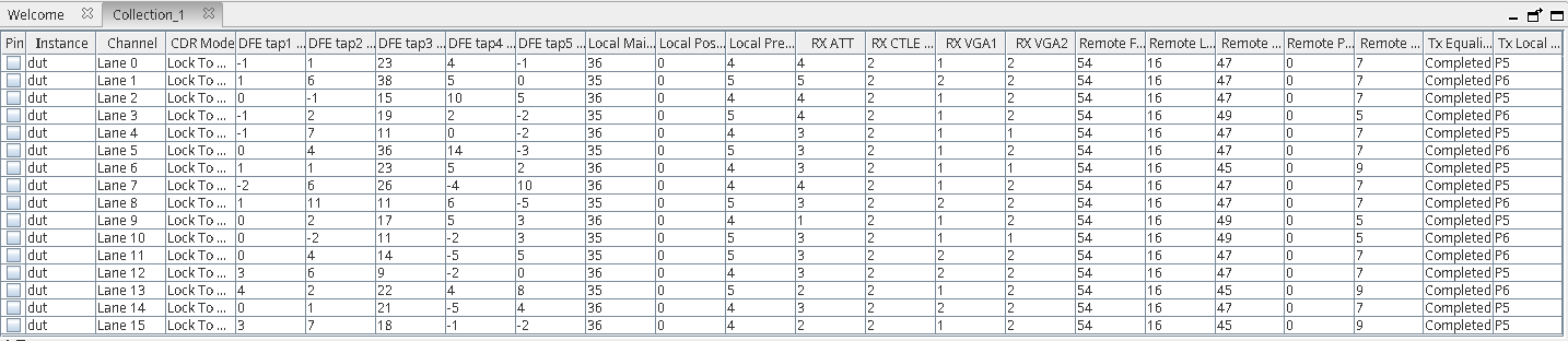
A. Main View
The main view tab lists a summary of the transmitter and receiver settings per channel for the given instance of the PCIe IP.
| Toolkit Channel | X16 Mode | 2X8 Mode | 4x4 Mode |
|---|---|---|---|
| Lane 0 | Lane 0 | Lane 0 | Lane 0 |
| Lane 1 | Lane 1 | Lane 1 | Lane 1 |
| Lane 2 | Lane 2 | Lane 2 | Lane 2 |
| Lane 3 | Lane 3 | Lane 3 | Lane 3 |
| Lane 4 | Lane 4 | Lane 4 | Lane 0 |
| Lane 5 | Lane 5 | Lane 5 | Lane 1 |
| Lane 6 | Lane 6 | Lane 6 | Lane 2 |
| Lane 7 | Lane 7 | Lane 7 | Lane 3 |
| Lane 8 | Lane 8 | Lane 0 | Lane 0 |
| Lane 9 | Lane 9 | Lane 1 | Lane 1 |
| Lane 10 | Lane 10 | Lane 2 | Lane 2 |
| Lane 11 | Lane 11 | Lane 3 | Lane 3 |
| Lane 12 | Lane 12 | Lane 4 | Lane 0 |
| Lane 13 | Lane 13 | Lane 5 | Lane 1 |
| Lane 14 | Lane 14 | Lane 6 | Lane 2 |
| Lane 15 | Lane 15 | Lane 7 | Lane 3 |
B. Toolkit Parameters
The Toolkit parameters window has the following sub-tabs.
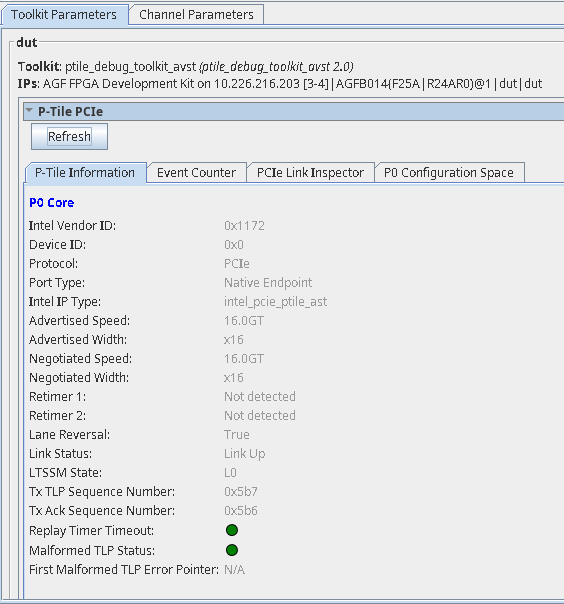
B.1. P-Tile Information
This lists a summary of the P-Tile PCIe IP parameter settings in the PCIe IP Parameter Editor when the IP was generated, as read by the P-Tile Debug Toolkit when initialized. If you have port bifurcation enabled in your design (for example, x8x8), then this tab will populate the P-tile information for each core (P0 core, P1 core, etc.).
All the information is read-only.
Use the Refresh button to read the settings.
| Parameter | Values | Descriptions |
|---|---|---|
| Intel Vendor ID | 1172 | Indicates the Vendor ID as set in the IP Parameter Editor. |
| Device ID | 0 | This is a unique identifier for the device that is assigned by the vendor. |
| Protocol | PCIe | Indicates the Protocol. |
| Port Type | Root Port, Endpoint 5 | Indicates the Hard IP Port type. |
| Intel IP Type | intel_pcie_ptile_ast, intel_pcie_ptile_avmm | Indicates the IP type used. |
| Advertised speed | Gen3, Gen4 | Indicates the advertised speed as configured in the IP Parameter Editor. |
| Advertised width | x16, x8, x4 | Indicates the advertised width as configured in the IP Parameter Editor. |
| Negotiated speed | Gen3, Gen4 | Indicates the negotiated speed during link training. |
| Negotiated width | x16, x8, x4 | Indicates the negotiated link width during link training. |
| Link status | Link up, link down | Indicates if the link (DL) is up or not. |
| LTSSM State | Refer to Hard IP Status Interface. | Indicates the current state of the link. |
| Lane Reversal | True, False | Indicates if lane reversal happens on the link. |
| Retimer 1 | Detected, not detected | Indicates if a retimer was detected between the Root Port and the Endpoint. |
| Retimer 2 | Detected, not detected | Indicates if a retimer was detected between the Root Port and the Endpoint. |
| Tx TLP Sequence Number | Hexadecimal value | Indicates the next transmit sequence number for the transmit TLP. |
| Tx Ack Sequence Timeout | Hexadecimal value | Indicates the ACK sequence number which is updated by receiving ACK/NAK DLLP. |
| Replay Timer Timeout | Green, Red | Green: no timeout Red: timeout |
| Malformed TLP Status | Green, Red | Green: no malformed TLP Red: malformed TLP detected |
| First Malformed TLP Error Pointer |
|
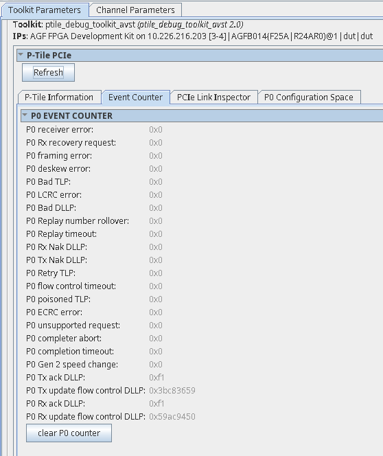
B.2. Event Counter
This tab allows you to read the error events like the number of receiver errors, framing errors, etc. for each port. You can use the Clear P0 counter/Clear P1 counter to reset the error counter.
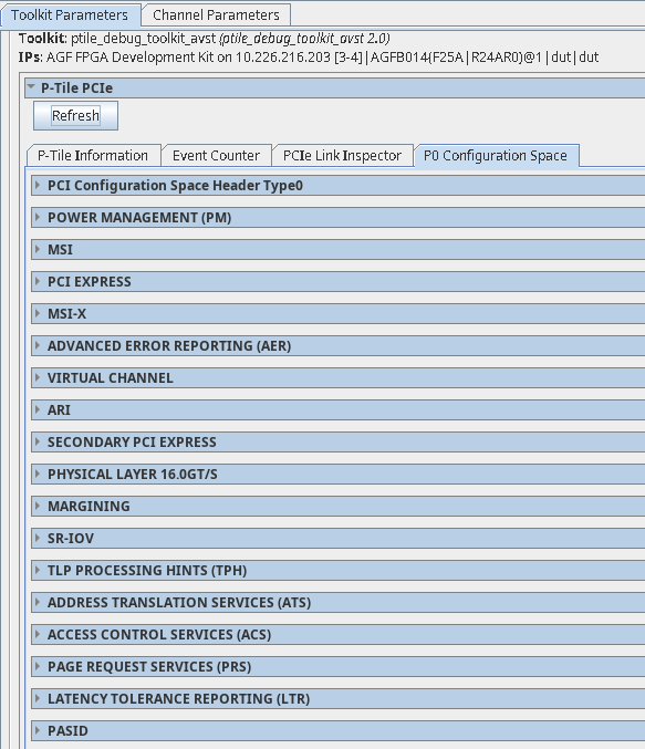
B.3. P0/P1 Configuration Space
This tab allows you to read the configuration space registers for that port. You will see a separate tab with the configuration space for each port.
C. Channel Parameters
The channel parameters window allows you to read the transmitter and receiver settings for a given channel. It has the following 3 sub-windows. Use the Lane Refresh button to read the status of the General PHY, TX Path, and RX Path sub-windows for each channel.
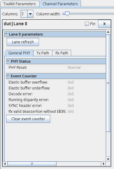
C.1. General PHY
This tab shows the reset status of the PHY.
| Parameters | Values | Descriptions | |
|---|---|---|---|
| PHY Status | PHY reset | Normal, Reset | Indicates the PHY is in reset mode. Normal: PHY is out of reset. Reset: PHY is in reset. |
| Event Counter 6 to clear the counter values. | Elastic buffer overflow | Hex value | Indicates elastic buffer overflow errors. |
| Elastic buffer underflow | Hex value | Indicates elastic buffer underflow errors. | |
| Decode error | Hex value | Indicates decode errors. | |
| Running disparity error | Hex value | Indicates running disparity errors. | |
| SYNC header error | Hex value | Indicates SYNC header errors. | |
| RX valid deassertion without EIEOS | Hex value | Indicates errors when RX valid deassertion occurs without EIEOS. |
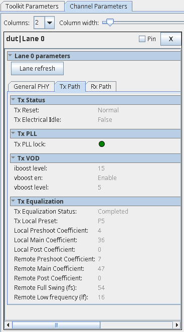
C.2. TX Path
This tab allows you to monitor the transmitter settings for the channel selected.
| Parameters | Values | Descriptions | |
|---|---|---|---|
| TX Status | TX Reset | Normal, Reset | Indicates if TX (TX datapath, TX settings) is in reset or normal operating mode. Normal: TX is in normal operating mode. Reset: TX is in reset. |
| TX Electrical Idle | True, False | Indicates if TX is in electrical idle. True: indicates TX is in electrical idle. False: indicates TX is out of electrical idle. |
|
| TX PLL | TX PLL lock | Green, Red | Indicates if TX PLL is locked. This is dependent on the PLL selected as indicated by TX PLL select.
There is one set of PLLs per Quad. The TX path of each channel reads out the PLL status corresponding to that Quad.
Green: TX PLL is locked. Red: TX PLL is not locked. |
| TX VOD | Iboost level | Gen3: 15 Gen4: 15 |
Indicates the transmitter current boost level when the TX amplitude boost mode is enabled. |
| Vboost en | Gen3: Enable Gen4: Enable |
Indicates if the TX swing boost level is enabled. Enable: TX swing boost is enabled. Disable: TX swing boost is disabled. |
|
| Vboost level | Gen3: 5 Gen4: 5 |
Indicates the TX Vboost level. | |
| TX Equalization | TX Equalization Status | Not attempted, Completed, Unsuccessful | Indicates transmitter equalization status. The TX local and remote parameters are valid only when the value of Equalization status is returned as completed, indicating equalization has completed successfully. |
| TX Local Preset | P0 to P10 | Indicates the P-tile transmitter driver preset value as requested by the link partner during the Equalization phase of link training. If the preset is not one of these values, then no value is shown. | |
| Local Pre-shoot coefficient | Depends on the coefficient requested by the link partner. |
Indicates P-tile transmitter driver output pre-emphasis (pre-cursor coefficient value). |
|
| Local main coefficient | Depends on the coefficient requested by the link partner. |
Indicates P-tile transmitter driver output pre-emphasis (main cursor coefficient value). |
|
| Local post coefficient | Depends on the coefficient requested by the link partner. |
Indicates P-tile transmitter driver output pre-emphasis (post-cursor coefficient value). |
|
| Remote Pre-shoot coefficient (†) | Depends on the transmitter driver output of the link partner. | Indicates link partner's transmitter driver's output pre-cursor coefficient value, as received by P-tile during the Equalization phase of link training. When P-tile is configured in Endpoint mode, this value corresponds to the coefficient received during Phase 2 of Equalization. |
|
| Remote main coefficient (†) | Depends on the transmitter driver output of the link partner. | Indicates link partner's transmitter driver's output main cursor coefficient value, as received by P-tile during the Equalization phase of link training. When P-tile is configured in Endpoint mode, this value corresponds to the coefficient received during Phase 2 of Equalization. |
|
| Remote post coefficient (†) | Depends on the transmitter driver output of the link partner. | Indicates the link partner's transmitter driver's output post-cursor coefficient value, as received by P-tile during the Equalization phase of link training. When P-tile is configured in Endpoint mode, this value corresponds to the coefficient received during Phase 2 of Equalization. | |
| Remote full swing (fs) (†) | Depends on the device capability of the link partner. | Indicates the full swing value used by the link partner during the Equalization phase of link training. | |
| Remote low frequency (lf) (†) | Depends on the device capability of the link partner. | Indicates the low frequency value used by the link partner during the Equalization phase of link training. |
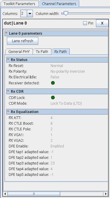
C.3. RX Path
This tab allows you to monitor and control the receiver settings for the channel selected.
| Parameters | Values | Descriptions | |
|---|---|---|---|
| RX Status | RX Reset | Normal, Reset | Indicates if RX (RX datapath, RX settings) is in reset or normal operating mode. Normal: RX is in normal operating mode. Reset: RX is in reset. |
| RX Polarity | No polarity inversion, Polarity inversion | Indicates RX polarity inversion for the selected lane. No polarity inversion: no polarity inversion on RX. Polarity inversion: polarity inversion on RX. |
|
| RX Electrical Idle | True, False | Indicates if RX is in electrical idle or not. True: RX is in electrical idle. False: RX is out of electrical idle. |
|
| Receiver Detected | Green, Grey | Green: Far end receiver is detected. Grey: Far end receiver is not detected. |
|
| RX CDR | CDR Lock | Green, Red | Indicates the CDR lock state. Green: CDR is locked. Red: CDR is not locked. |
| CDR Mode | Locked to Reference (LTR), Locked to Data (LTD) | Indicates the CDR lock mode. LTR: CDR is locked to reference clock. LTD: CDR is locked to data. |
|
| RX Equalization | RX ATT | Gen3: 0 Gen4: 0 |
Indicates the RX equalization attenuation level. |
| RX CTLE Boost | Gen3: 12 Gen4: 16 |
Indicates the RX CTLE boost value. |
|
| RX CTLE Pole | Gen3: 2 Gen4: 2 |
Indicates the RX CTLE pole value. |
|
| RX VGA1 | Gen3: 5 Gen4: 5 |
Indicates the RX AFE first stage VGA gain value. |
|
| RX VGA2 | Gen3: 5 Gen4: 5 |
Indicates the RX AFE second stage VGA gain value. |
|
| DFE Enable | Enable, Disable | Indicates DFE adaptation is enabled for taps 1 - 5. Enable: DFE adaptation is enabled for taps 1 - 5. Disable: DFE adaptation is disabled for taps 1 - 5. |
|
| DFE Tap1 adapted value | <-128 to 127> | Indicates the adapted value of DFE tap 1. This is a signed input (two's complement encoded). |
|
| DFE Tap2 adapted value | <-32 to 31> | Indicates the adapted value of DFE tap 2. This is a signed input (two's complement encoded). |
|
| DFE Tap3 adapted value | <-32 to 31> | Indicates the adapted value of DFE tap 3. This is a signed input (two's complement encoded). |
|
| DFE Tap4 adapted value | <-32 to 31> | Indicates the adapted value of DFE tap 4. This is a signed input (two's complement encoded). |
|
| DFE Tap5 adapted value | <-32 to 31> | Indicates the adapted value of DFE tap 5. This is a signed input (two's complement encoded). |
D. Eye Viewer
- Provides a pictorial representation of the eye for each channel, both in the bifurcated (e.g., x8x8) and non-bifurcated (e.g., x16) configurations.
-
Provides information on the total eye height, total eye width and the eye margin from the sampling point to the left, right, top, and bottom of the eye for each lane.
Intel recommends that the margin for each lane on your board be more than the mask in the horizontal and vertical directions to make sure that the channel is good and meets the PCIe specification.
- Uses fixed step sizes in the horizontal and vertical directions.
- Performs the eye margin at the following bit error rates (BER):
- 8.0 GT/s (Gen3) @ e-8, 100% confidence level
- 16.0 GT/s (Gen4) @ e-9, 90% confidence level
- 8.0 GT/s (Gen3) and 16.0 GT/s (Gen4) @ e-12, 95% confidence level
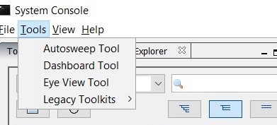
- In the System Console Tools menu option, click on Eye View Tool.
Note: The per-lane information under the Eye Viewer tab corresponds to the physical lanes.Figure 76. Opening the Eye Viewer
- This will open a new tab Eye View Tool next to the Main View tab. Choose the instance and channel for which you want to run the eye view tests.
Figure 77. Opening the Instance and Channel
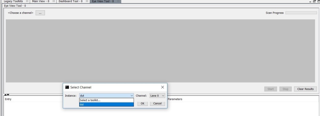
- Set the Eye Max BER. Two options are available: 1e-9 or 1e-12.
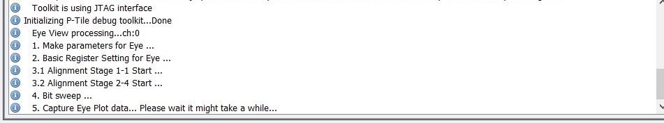
- Click Start to begin the eye measurement for the selected channel.
- The messages window displays information messages to indicate the eye view tool's progress.
Figure 78. Eye View Tool Messages
- Once the eye plot is complete, the eye height, eye width and eye diagram are displayed.
Figure 79. Sample Eye Plot for BER = 1e-9
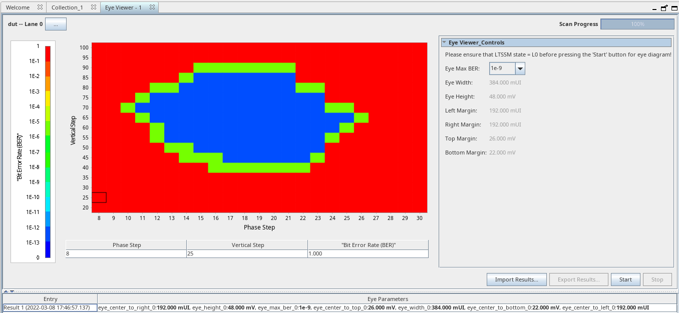 Figure 80. Sample Eye Plot for BER = 1e-12
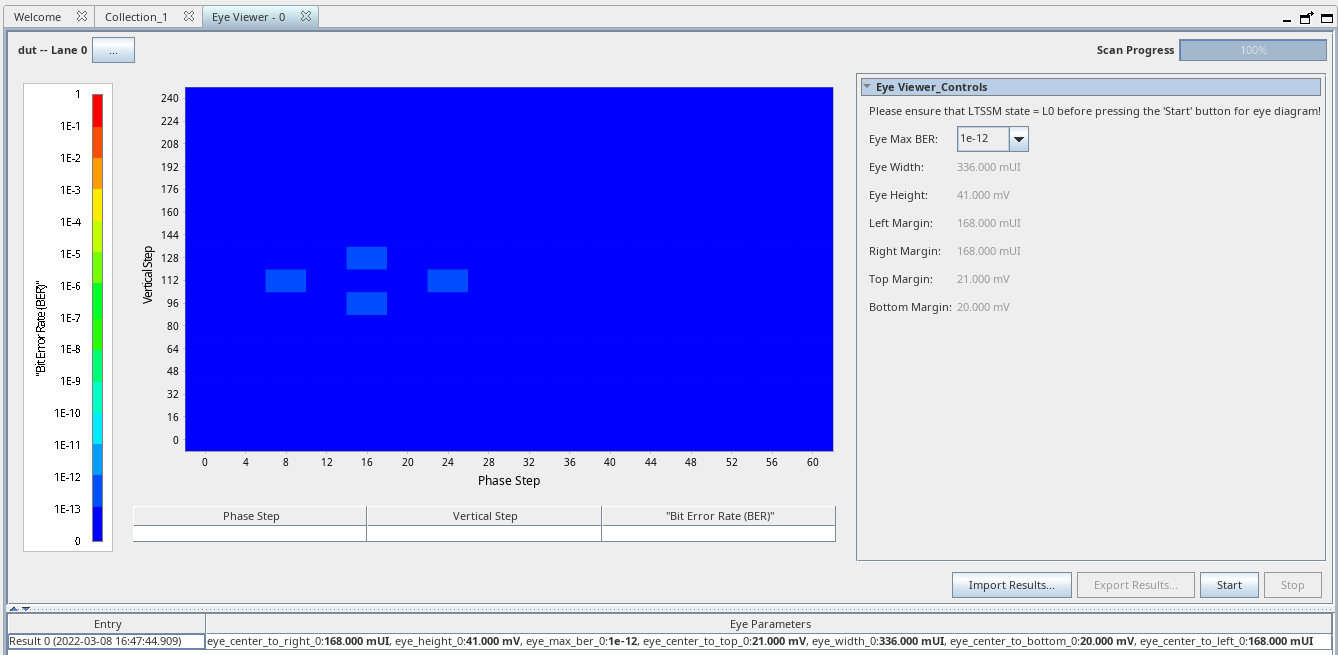 Note: Full eye plot is not drawn for BER = 1e-12.