Developer Guide
FPGA Optimization Guide for Intel® oneAPI Toolkits
A newer version of this document is available. Customers should click here to go to the newest version.
Pipelining
Pipelining is a design technique used in synchronous digital circuits to increase fMAX. Pipelining involves adding registers to the critical path, which decreases the amount of logic between each register. Less logic takes less time to execute, which enables an increase in fMAX.
The critical path in a circuit is the path between any two consecutive registers with the highest latency. That is, the path between two consecutive registers where the operations take the longest to complete.
Pipelining is especially useful when processing a stream of data. A pipelined circuit can have different stages of the pipeline operating on different input stream data in the same clock cycle, which leads to better data processing throughput.
Example
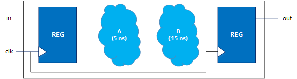
Consider a simple circuit with operations A and B on the critical path. If operation A takes 5 ns to complete and operation B takes 15ns to complete, then the time delay on the critical path is 20 ns. This results in an fMAX of 50 MHz (1/max_delay).
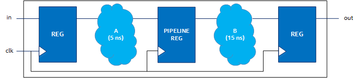
If a pipeline register is added between A and B, the critical path changes. The delay on the critical path is now 15ns. Pipelining this block results in an fMAX of 66.67 MHz, and the maximum delay between two consecutive registers is 15 ns.
While pipelining generally results in a higher fMAX, it increases latency. In the previous example, the latency of the block containing A and B increases from two to three clock cycles after pipelining.